YG100R_Mainte_E.pdf - 第48页
3-10 3 Periodic maintenance items 1 . 2 . 4 R e a s s e m b l i n g t h e F N C n o z z l e a s s e m b l y W h e n f i n i s h e d c l e a n i n g t h e F N C n o z z l e a s s e m b l y a n d F N C l o c k p i n , r e …
3-9
3
Periodic maintenance items
1.2.3 Cleaning the FNC lock pin
Inside the spline shaft of each YG100RA FNC head, a lock pin (or locate pin) is used to lock the rotation of the
FNC nozzle assembly when the selected nozzle points downwards. If dust or grime adheres to this lock pin,
component pickup or mount errors tend to occur. Although depending on the operation time, we recommend
cleaning the lock pin at the time when you take apart and clean the FNC nozzle assembly.
1
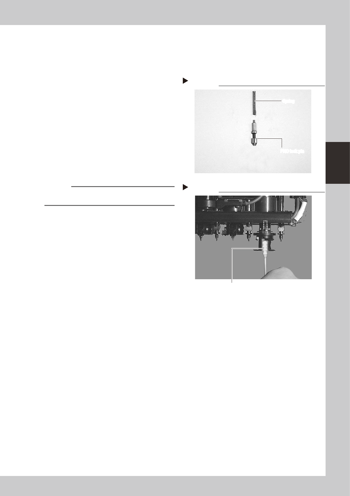
Clean the FNC lock pin parts.
Wipe the FNC lock pin and spring with a
lint-free cleaning cloth moistened with
alcohol.
53377-F9-00
2
Clean the FNC lock pin insertion
hole.
1. Blow air into the air path of the FNC lock
pin insertion section of the spline shaft.
2. Wipe inside the FNC lock pin insertion
section thoroughly with a lint-free cotton
swab moistened with alcohol.
53379-F9-00
Reference
Use spiral-tip cotton swabs (thickness: 4mm or less) that
are commercially available.
3
Lubricate the FNC lock pin.
Using the lubrication syringe (KV8-M8870-
00X) and turbine oil (VG32), apply one or
two drops of oil to the FNC lock pin and then
spread it with your finger.
4
Reinstall the FNC lock pin and
spring.
Advance to the next section 1.2.4,
"Reassembling the FNC nozzle assembly".
FNC lock pin and spring removed from head
Step 1
FNC lock pin
Spring
FNC lock pin
Spring
Cleaning the FNC lock pin insertion section
Step 2
Wipe with cotton swab/bud moistened with alcohol.
3-10
3
Periodic maintenance items
1.2.4 Reassembling the FNC nozzle assembly
When finished cleaning the FNC nozzle assembly and FNC lock pin, reassemble them as explained below.
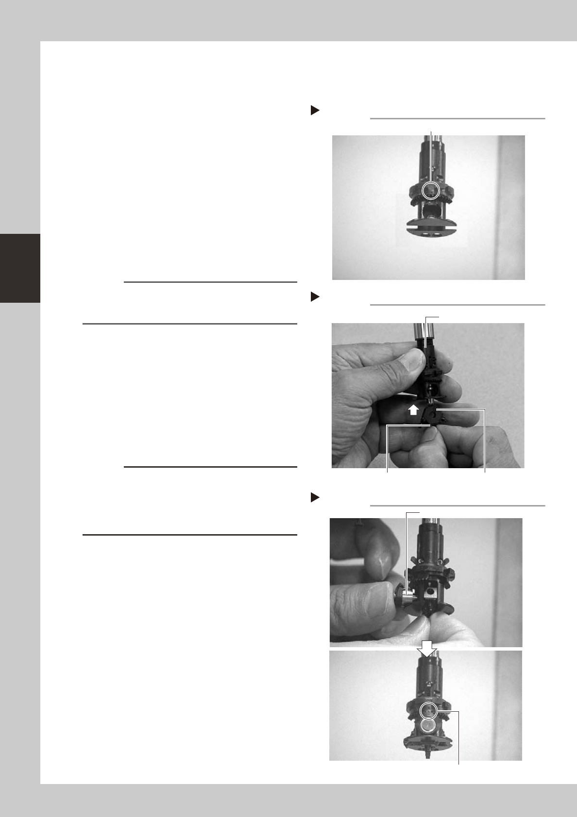
1
Rotate the spline shaft so the mark
in the middle of the index holder
faces the front.
53381-F9-10
2
Reassemble the FNC nozzle
assembly.
Insert, in order, the spring, FNC lock pin and
FNC nozzle assembly into the holder. At this
point, hold the FNC nozzle assembly with the
cutout facing towards the front and Type
212F nozzle pointing downwards, and insert
each part up into the index holder.
53353-F9-10
n
NOTE
Before inserting the FNC lock pin, make sure that the
small cams above the index holder are retracted
upwards.
3
Insert the bevel gear and shaft into
the center of the FNC nozzle
assembly.
While slightly pressing the FNC nozzle
assembly up, insert the bevel gear and shaft
into the center hole of the FNC nozzle
assembly from the front, and align the mark
on the bevel gear with the mark on the
index holder.
53354-F9-10
c
CAUTION
Reassemble the nozzle assembly, bevel gear and shaft
in their original combination for each FNC head, without
mixing them with parts for other heads. If this
combination is changed, the bevel gear may not rotate
smoothly or the pickup vacuum level may drop.
Positioning so the mark faces the front
Step 1
This mark should face the front.
Inserting the FNC nozzle assembly
Step 2
Type 212F nozzle should be pointed downwards. Cutout
Index holder
Inserting the bevel gear and shaft
Step 3
Insert the shaft.
Align marks with each other.
3-11
3
Periodic maintenance items
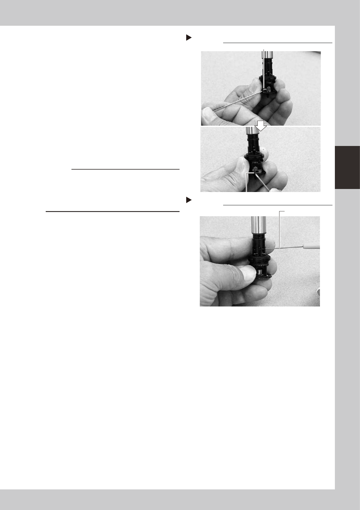
4
Secure the FNC nozzle assembly.
1. Turn the index holder so that the bevel
gear faces the opposite side.
2. Align the surface of the bevel gear shaft
horizontally and slide the stopper block
back to the original position. Then tighten
the bolt with the M1.5 hex wrench to
secure the stopper block.
3. Rotate the spline shaft so the bevel gear
faces the front. With the spline shaft
lowered, use the dedicated hex wrench
(0.7) to tighten the set screw that
prevents one of the lock pin cams from
being retracted in the shaft.
53355-F9-10
53356-F9-10
c
CAUTION
• When tightening the stopper block screws, hold the
edge of the FNC assembly so it won't rotate.
• The screwdriver bit size may slightly differ between
manufacturers. Use the screwdriver that matches
the recessed pattern on the screw head.
Securing the FNC nozzle assembly
Step 4-2
Position the flat face of shaft horizontally.
Secure the stopper block with the hex wrench.
Tightening the set screw for lock pin cam
Step 4-3
Dedicated hex wrench