PC200_Manual_REV_G-1.pdf - 第10页
PC200 PVA Revis ion G (201 9) 10 of 56 Valve O pera tion Startup 1. Inst all the v al ve pneumatically as show n in S ec tion 1.5 and set the air pressure that op erat es the valve be tween 60-10 0 p si. 2. Cycle the v a…
PC200
PVA
Revision G (2019)
9 of 56
Overview
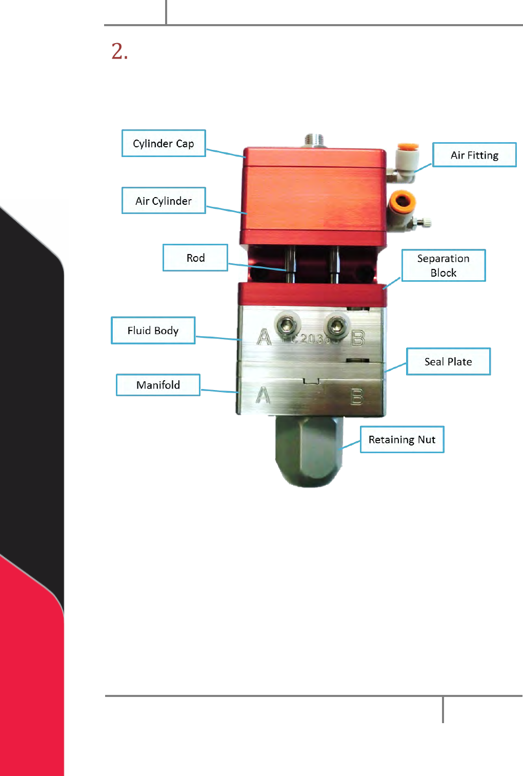
Before you operate the valve, know the valve components. Examine the valve
components shown below for safe and correct operation.
Figure 2: Valve Components
PC200
PVA
Revision G (2019)
10 of 56
Valve Operation
Startup
1. Install the valve pneumatically as shown in Section 1.5 and set the air
pressure that operates the valve between 60-100 psi.
2. Cycle the valve several times. Make sure that the valve is not pointed at
anyone.
When the valve cycles correctly, you can hear the piston hit the stroke adjustment
screw and the rods can be seen going up and down in the center.
NOTE: If the valve does not cycle correctly, refer to Section 11.
3. Connect the material delivery system to the valve. Part A material
connects on the on the left side, part B material connects on the right side.
4. Cycle the valve open to bleed. Part A and B materials should start to
flow separately out of the fluid manifold.
5. Bleed the valve until all the air is released, and the material releases
smoothly without any breaks in the flow. Any break in the flow of the
material shows there is still air in the system.
6. Ble
ed air from the bleed screws if necessary.
NOTE: Part A and B materials may not start to dispense from the valve at
the same time, flow depends on the necessary mix ratio.
7. Use a 3/16” hex key to adjust the stroke adjustment screw to get the
necessary amount of snuff back.
Turn the stroke adjustment screw clockwise to decrease the amount of snuff back,
or counter-clockwise to increase the amount of snuff back. If the stroke adjustment
screw is turned down too far the valve will not close and material will leak from the
manifold nozzle.
NOTE: A good general setting for snuff back is to turn the stroke
adjustment screw clockwise until material starts to leak from the valve
manifold when under pressure, then turn the stroke adjustment screw a ½
turn counter-clockwise or until it does not leak.
8. When snuff back is set, use an adjustable wrench to tighten the jam nut
against the sealing washer and cylinder cap to lock it in place.
NOTE: Refer to Section 11 for any other problems.
PC200
PVA
Revision G (2019)
11 of 56
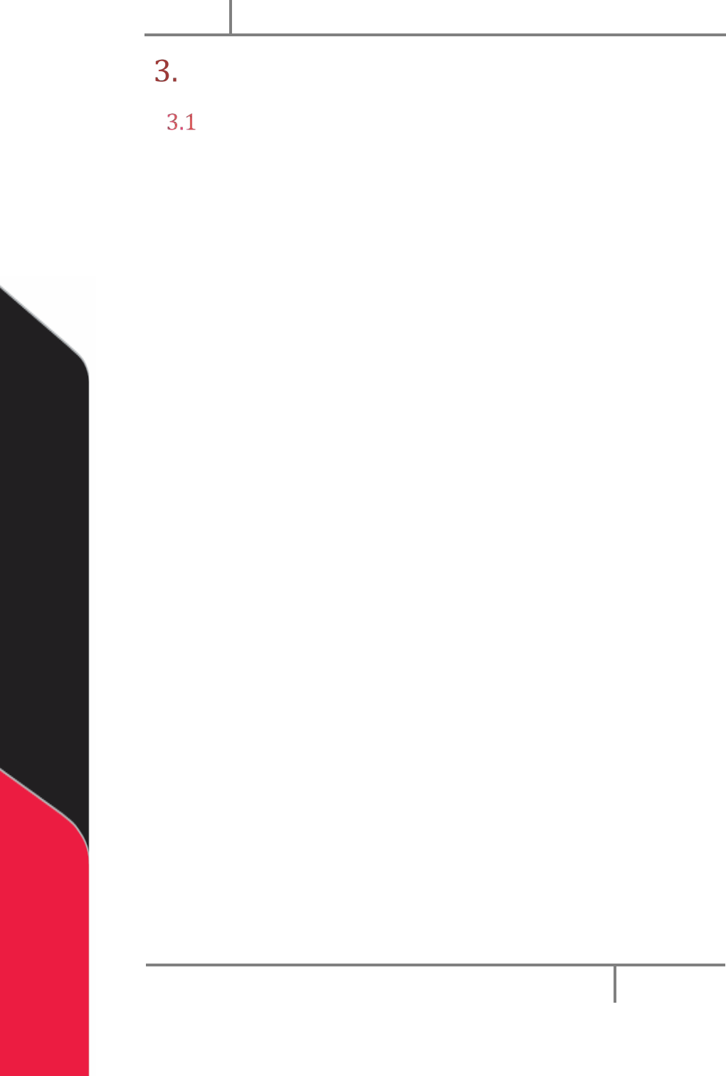
Install the Static Mixer
1. Put the static mixer on the PC200 valve manifold as shown.
Figure 3: Static Mixer
2. Hold the static mixer on the PC200 manifold with your hand.
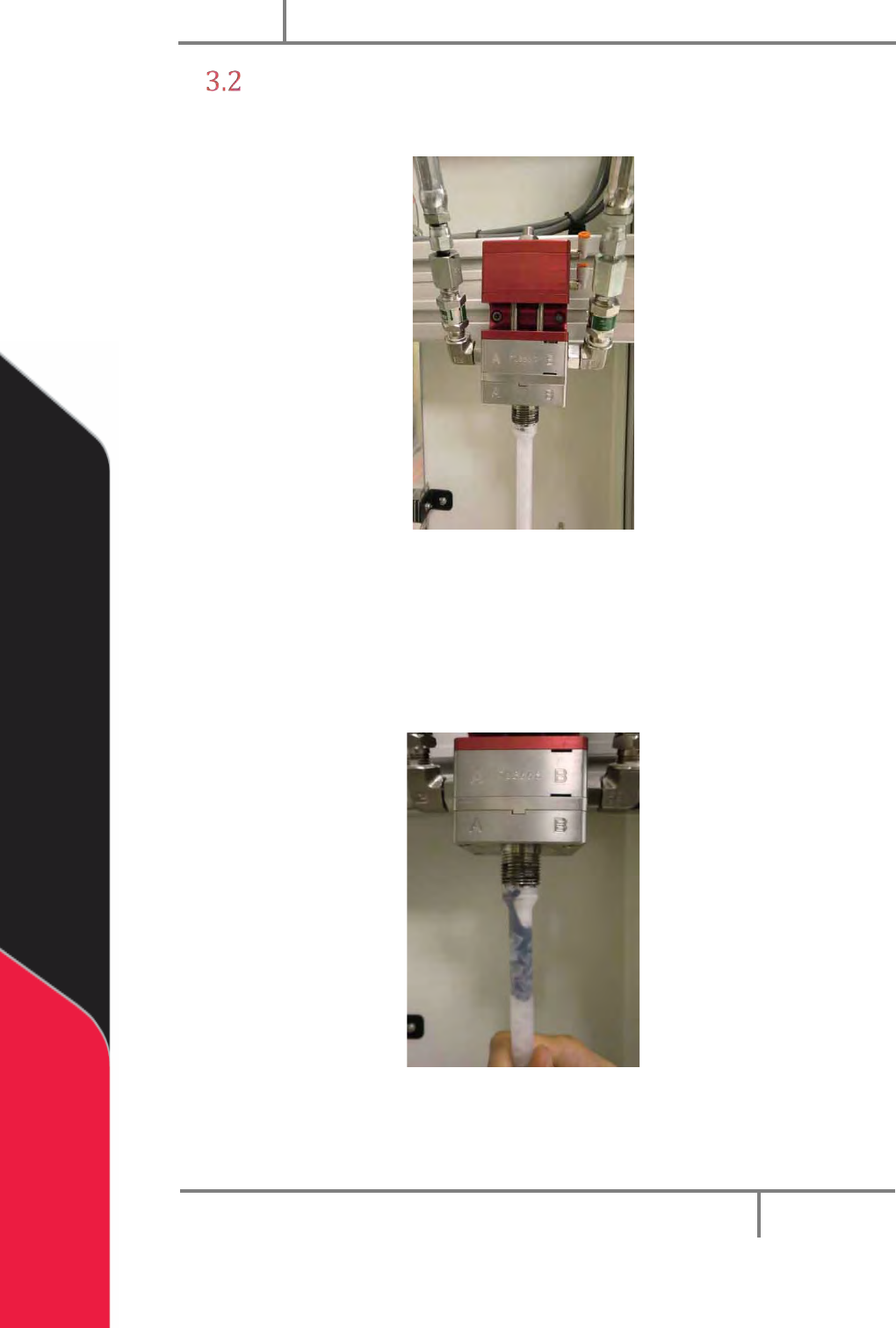
3. Use the purge function (in Manual mode) on the machine controller to
purge material through the static mixer.
4. Continue to purge until the static mixer is fully filled with material.
Figure 4: Fill the Static Mixer
Now the trapped air must be released from the top of the static mixer.