PC200_Manual_REV_G-1.pdf - 第18页
PC200 PVA Revis ion G (201 9) 18 of 56 18. Pull the air c ylinder, separation block, and fluid section apart. Fig ure 18 : Disconnect Valv e Sections 19. Examine the sle eve bearings in the s eparation block for damage o…
PC200
PVA
Revision G (2019)
17 of 56
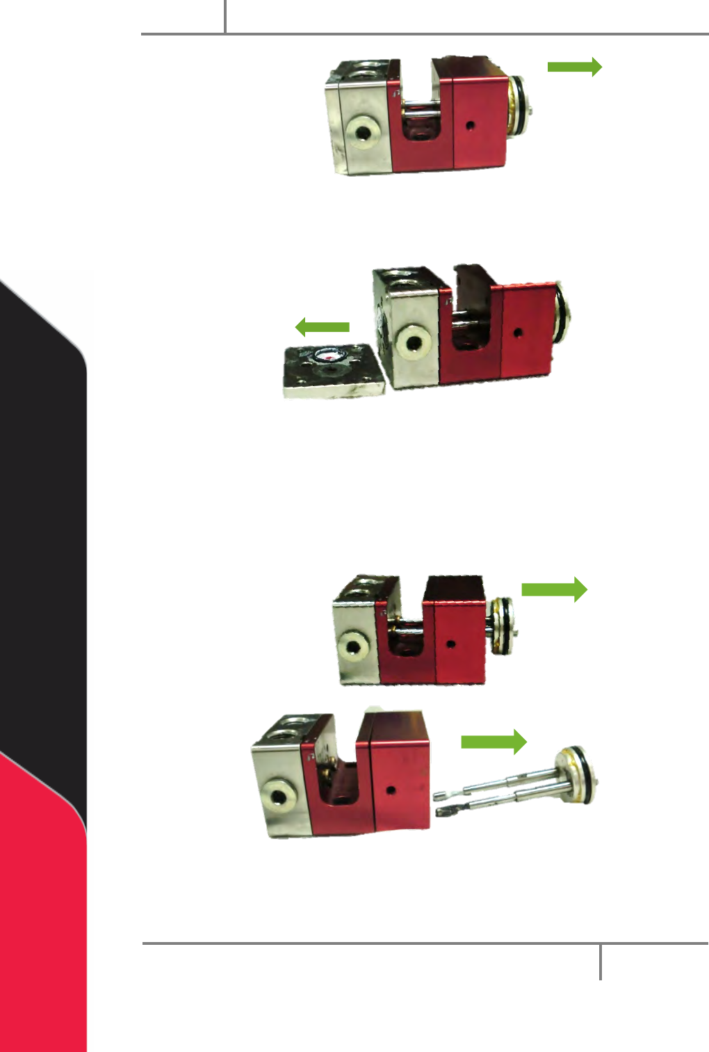
Figure 15: Disengaged Piston-Rod Assembly
14. Remove the seal plate.
Figure 16: Seal Plate Removed
15. Remove and clean the O-rings in between the seal plate and the fluid
section.
16. Remove and clean the lip seals in the fluid section.
17. Pull the piston-rod assembly out of the air cylinder.
Figure 17: Piston-Rod Assembly Removed
NOTE: RW-series PC200 uses two different size rods.
PC200
PVA
Revision G (2019)
18 of 56
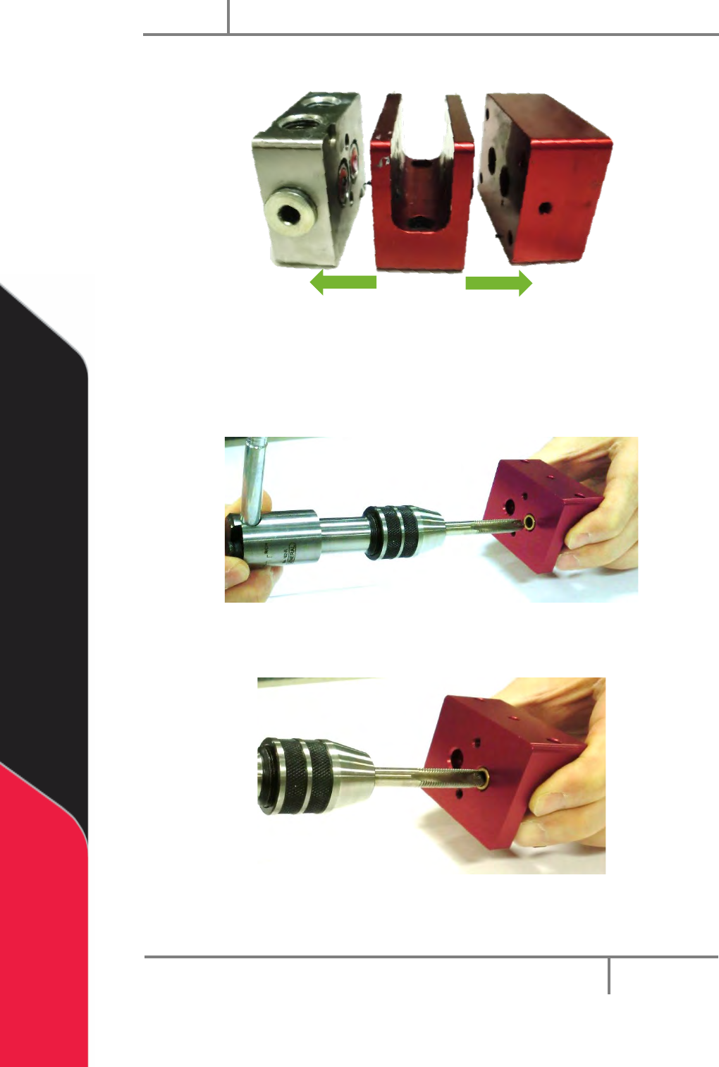
18. Pull the air cylinder, separation block, and fluid section apart.
Figure 18: Disconnect Valve Sections
19. Examine the sleeve bearings in the separation block for damage or wear. If
there is any sign of wear replace them.
20. To remove the sleeve bearings, install a correctly sized tap into the sleeve
bearing in the bottom of the separation block.
Figure 19: Install the Tap into the Sleeve Bearing
21. Push the tap in and turn it clockwise to engage the tap in the sleeve bearing.
Figure 20: Engage the Tap into the Sleeve Bearing
PC200
PVA
Revision G (2019)
19 of 56
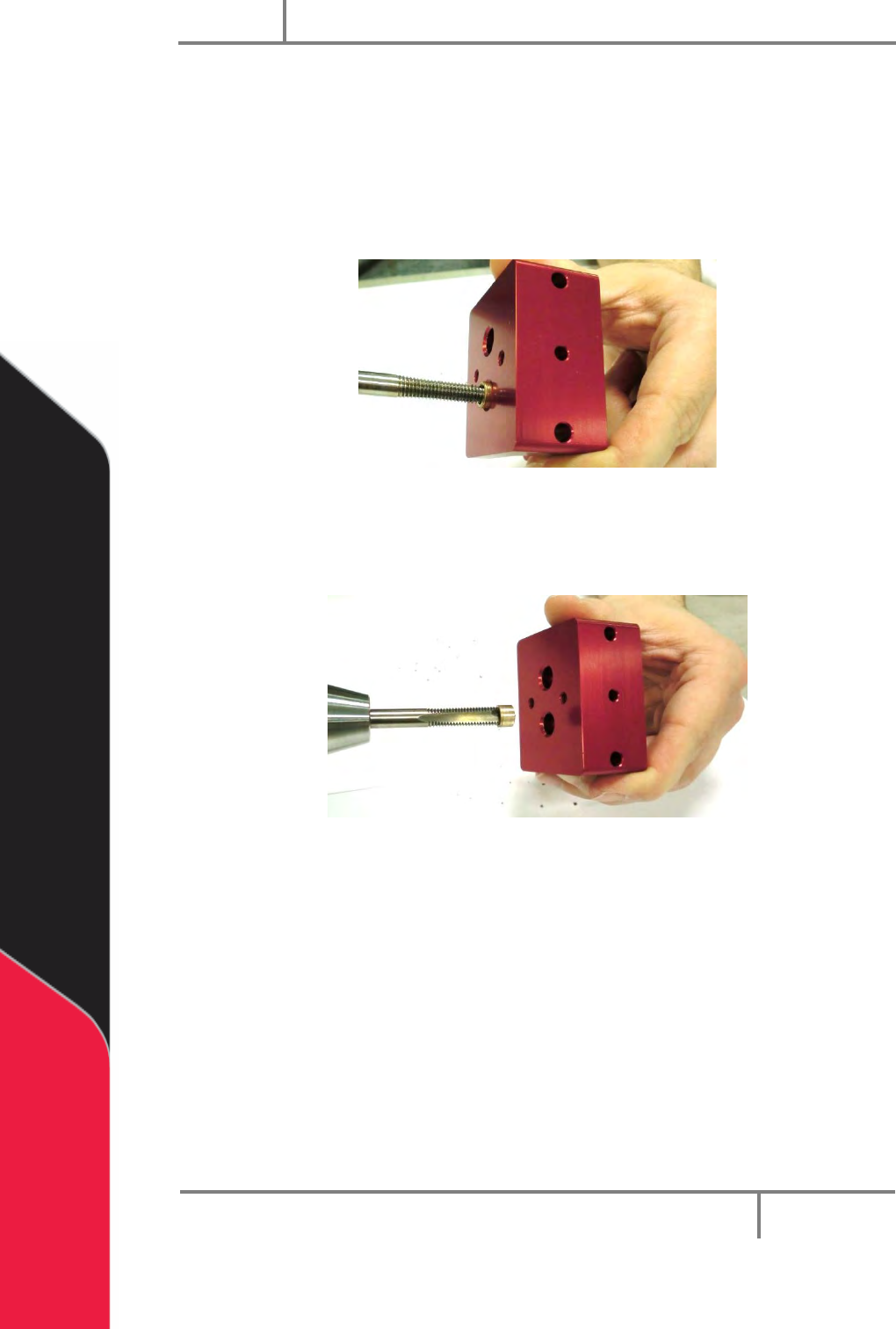
WARNING: Do not let the tap go through the sleeve bearing and into the
separation block.
22. Continue to turn the tap clockwise and push in until the sleeve bearing starts to
spin when you turn the tap.
23. Continue to turn the tap clockwise and pull out as you turn. The sleeve bearing
will start to pull out of the separation block.
Figure 21: Turn the Tap and Pull Out
24. Pull the sleeve bearing out of the separation block. Do the procedure again for
the other sleeve bearing.
Figure 22: Remove the Sleeve Bearing
25. Clean any pieces of the sleeve bearings from the separation block.
26. Use the hook and pick set to remove the lips seals and the O-rings from the
fluid section.