PC200_Manual_REV_G-1.pdf - 第16页
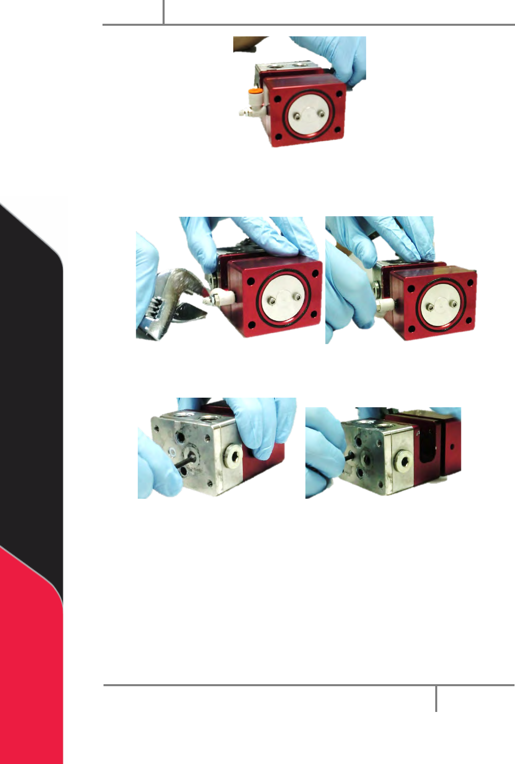
PC200 PVA Revis ion G (201 9) 16 of 56 Fig ure 12 : Air Cy l inder wi thout Air C ap 11. Use a wr ench t o loo sen the air fit tings an d then use your hand to remove them. Fig ure 13 : Remove Air Fitti ngs 12. Use a cor…
PC200
PVA
Revision G (2019)
15 of 56
Figure 9: Disassembled Fluid Manifold
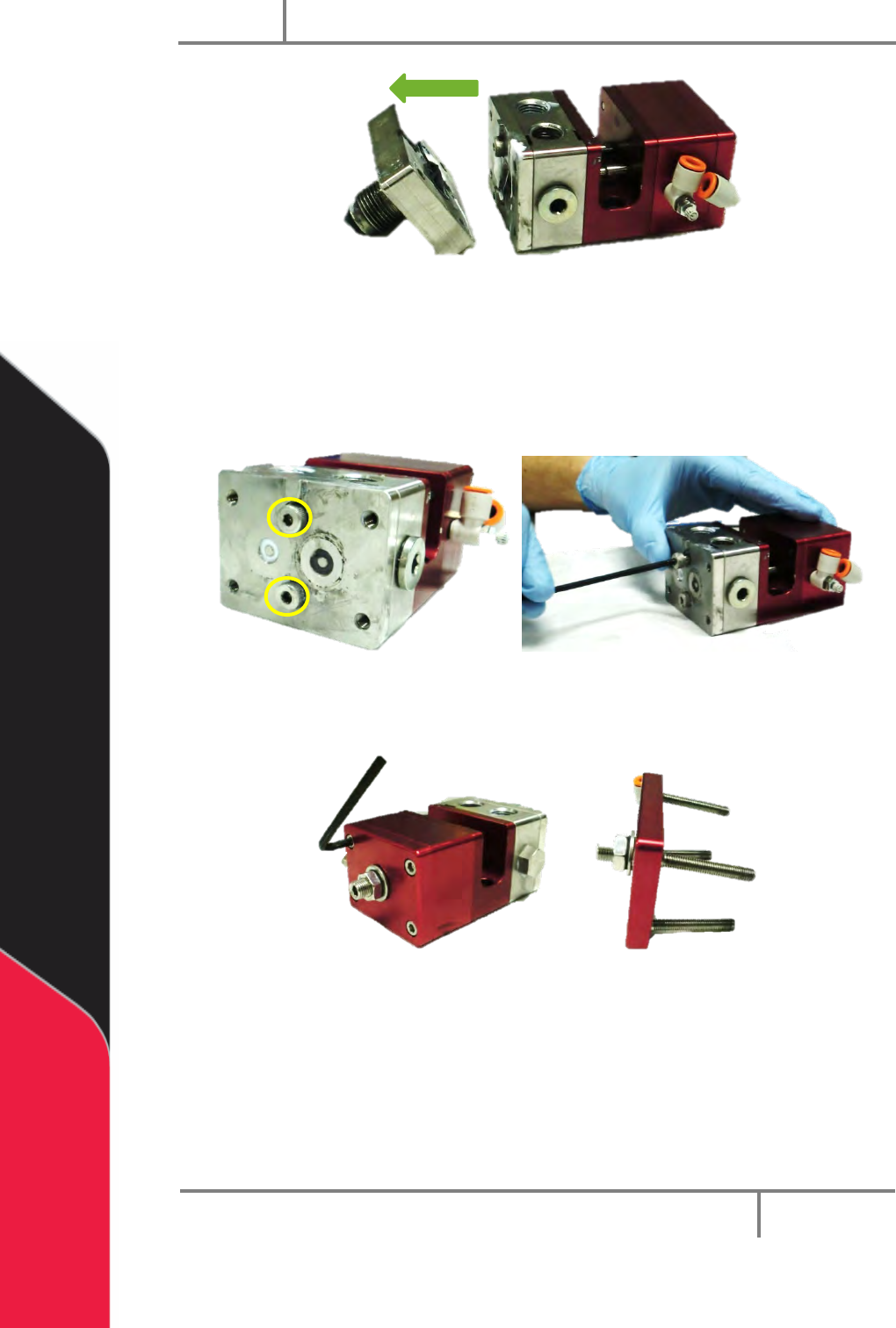
6. Remove the O-rings in the fluid manifold.
7. Clean the O-rings and examine them for damage.
8. Use a hex key to remove the two shoulder bolts from the seal plate.
Figure 10: Valve Shoulder Bolts
9. Use a hex key to remove the four machine screws from the air cap.
Figure 11: Remove Air Cap Screws
10. Remove the air cap.
PC200
PVA
Revision G (2019)
16 of 56
Figure 12: Air Cylinder without Air Cap
11. Use a wrench to loosen the air fittings and then use your hand to remove
them.
Figure 13: Remove Air Fittings
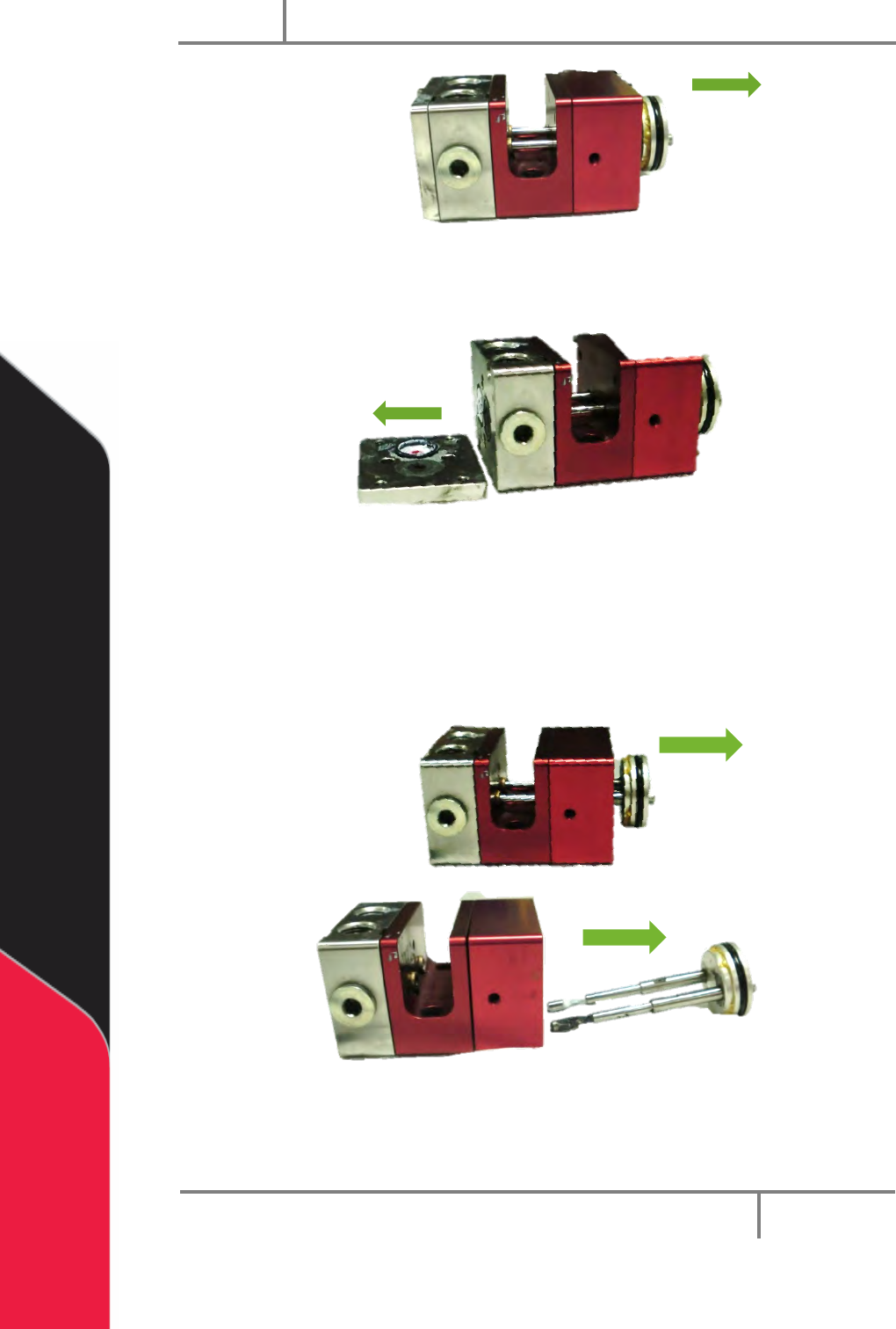
12. Use a correctly sized hex key to push on the rods engaged in the seal plate.
Figure 14: Push Rods to Disengage
13. Push on the rods one at a time until the piston-rod assembly disengages
from the air cylinder.
PC200
PVA
Revision G (2019)
17 of 56
Figure 15: Disengaged Piston-Rod Assembly
14. Remove the seal plate.
Figure 16: Seal Plate Removed
15. Remove and clean the O-rings in between the seal plate and the fluid
section.
16. Remove and clean the lip seals in the fluid section.
17. Pull the piston-rod assembly out of the air cylinder.
Figure 17: Piston-Rod Assembly Removed
NOTE: RW-series PC200 uses two different size rods.