PC200_Manual_REV_G-1.pdf - 第14页
PC200 PVA Revis ion G (201 9) 14 of 56 Disassemble t he Valve This sec tion sho w s how to disa ssem ble PC2 00 val ves ( Std. PC200 R pro ces s is s ho wn) . Some steps that involve rods, lip seals, sleev e bearings, an…
PC200
PVA
Revision G (2019)
13 of 56
Shutdown
To keep the PC200 valve in good condition do these steps at the end of each day:
1. Remove the static mixer.
2. Purge fresh material through the valve until both material streams are
completely clean and have no cross-contamination.
3. Clean all material off of the manifold nozzle.
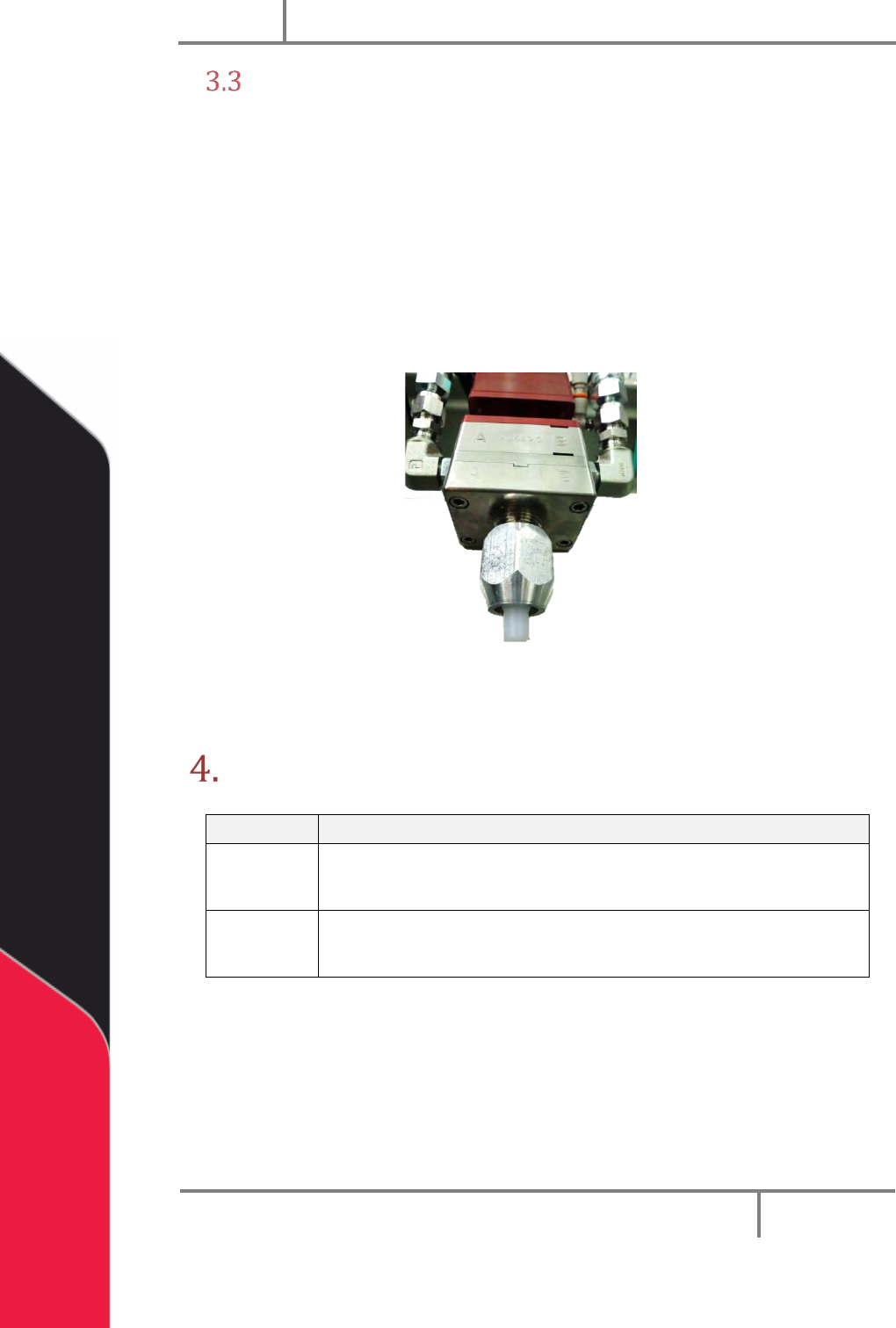
4. Put a night cap (PVA part number 214-3832) on the manifold nozzle.
5. Release the pressure in the system, refer to the workcell manual.
Figure 6: PC200 Night Cap
NOTE: Refer to Sections 6 and 7 for part reference numbers.
Maintenance
Interval
Action
Daily
• Examine the material outlets for contamination and cured
material.
Weekly
• Examine component A and B material containers or cartridges
for signs of cured or dried material.
Before you do maintenance on this valve, make sure you have a spare parts kit. If any
parts have wear or damage, replace them with new parts from the kit.
PC200
PVA
Revision G (2019)
14 of 56
Disassemble the Valve
This section shows how to disassemble PC200 valves (Std. PC200R process is
shown). Some steps that involve rods, lip seals, sleeve bearings, and O-rings will
differ between the R and RW series of the PC200. Not all options are shown. When
procedures are different from what is shown, “Notes” are given. If you have
questions about procedure steps, parts, or content, contact PVA’s customer service
department.
Procedure
Put valve sections, seals, parts, and screws in solvent to soak if material can be seen on
them. Do not combine materials A and B or they will cure. Examine all parts for wear
and damage. Replace parts if necessary.
1. Relieve system pressure. Disconnect material and air fittings. Disconnect the
valve from the dispense system.
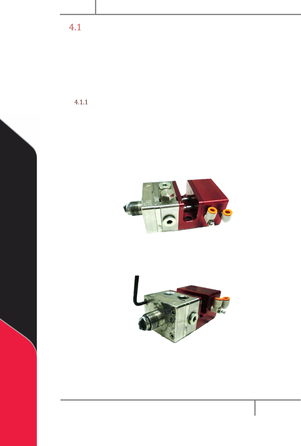
2. Remove the retaining nut and the static mixer and needle.
Figure 7: PC200 Ready for Disassembly
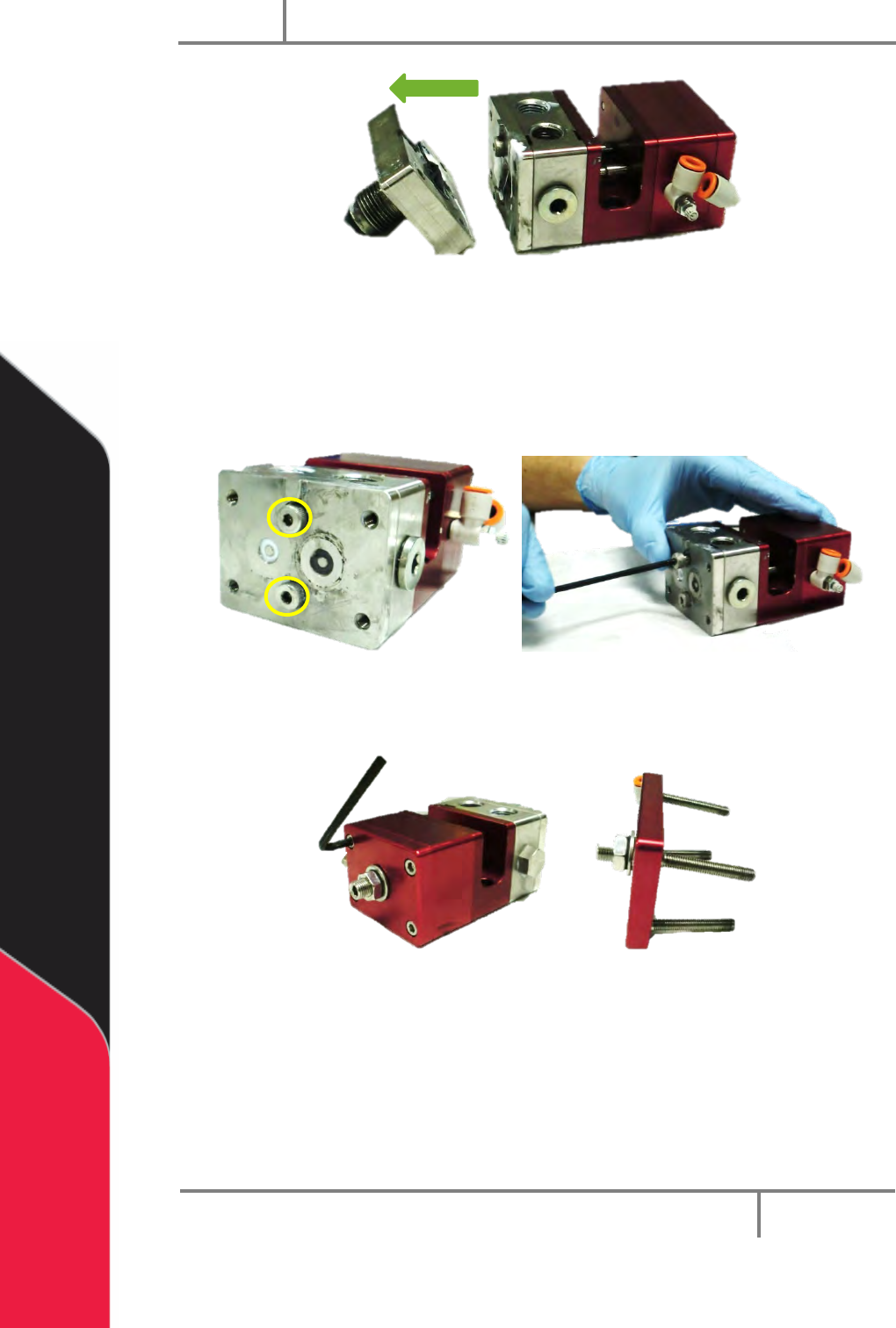
3. Remove front bleed port plugs if necessary.
4. Use a hex key to remove the four machine screws in the fluid manifold.
Figure 8: Fluid Manifold Screws
5. Pull the manifold off of the valve assembly.
PC200
PVA
Revision G (2019)
15 of 56
Figure 9: Disassembled Fluid Manifold
6. Remove the O-rings in the fluid manifold.
7. Clean the O-rings and examine them for damage.
8. Use a hex key to remove the two shoulder bolts from the seal plate.
Figure 10: Valve Shoulder Bolts
9. Use a hex key to remove the four machine screws from the air cap.
Figure 11: Remove Air Cap Screws
10. Remove the air cap.