PC200_Manual_REV_G-1.pdf - 第31页
PC200 PVA Revis ion G (201 9) 31 of 56 Fig ure 53 : Sea ling Washe r 35. Put th e jam nut on th e stroke adjus tmen t screw an d t u rn it until it is tight to the sealing washer. Fig ure 54 : Ja m Nut 36. Put th e cyl i…
PC200
PVA
Revision G (2019)
30 of 56
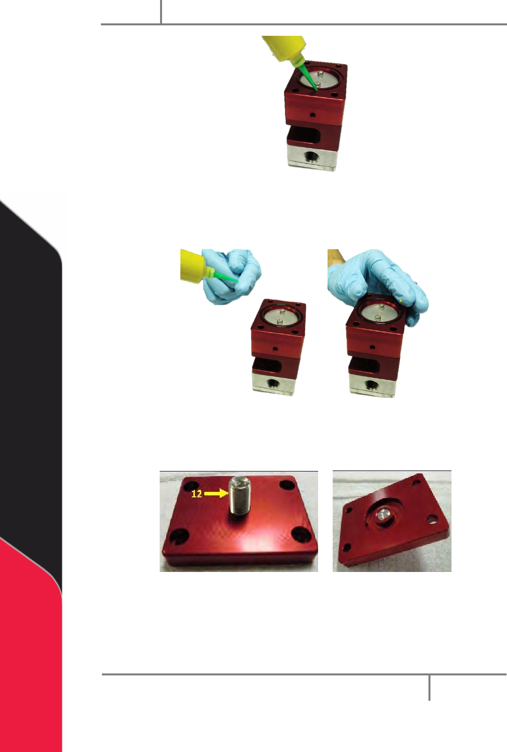
Figure 50: Apply Grease to Air Cylinder Groove
31. Install a 030 Buna O-ring in the air cylinder groove.
32. Apply grease to the top of the installed O-ring with your finger.
Figure 51: Apply Grease to O-ring
33. Use a 3/16” hex key to tighten the stroke adjustment screw on the cylinder
cap.
Figure 52: Tighten Stroke Adjustment Screw
34. Put the sealing washer on the stroke adjustment screw and slide it down to
the cylinder cap.
PC200
PVA
Revision G (2019)
31 of 56
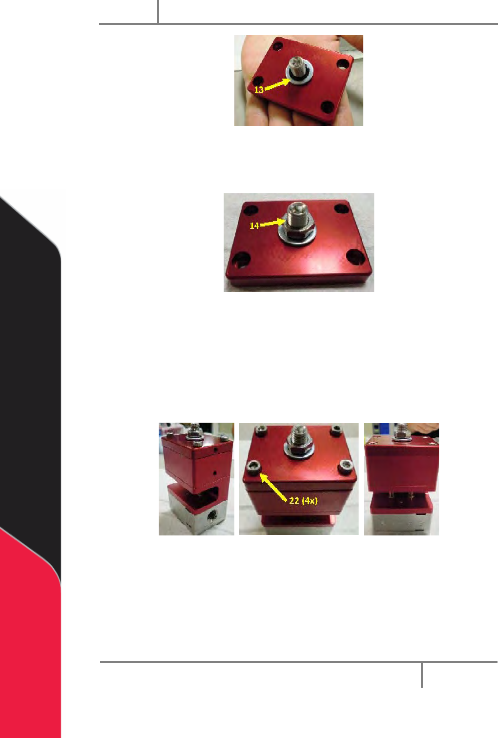
Figure 53: Sealing Washer
35. Put the jam nut on the stroke adjustment screw and turn it until it is tight to
the sealing washer.
Figure 54: Jam Nut
36. Put the cylinder cap on the air cylinder.
37. Install the four machine screws.
38. Use a 5/32” hex key to tighten the screws to the separation block.
NOTE: Line up the air hole on the cylinder on the right side of the separation
block.
Figure 55: Cylinder Cap Installed on the Valve
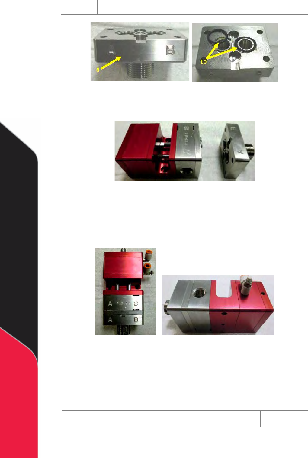
39. Apply silicone grease to two 016 O-rings and put them in the grooves of the
fluid manifold.
PC200
PVA
Revision G (2019)
32 of 56
Figure 56: O-rings in the Fluid Manifold
40. With the lettering on the front, put the fluid manifold on the seal plate and
install four machine screws.
Figure 57: Fluid Manifold Aligned with Valve
41. Use a 5/32” hex key to tighten the screws.
42. The PC200 valve and its mechanical portion are now assembled.
43. Additional air and fluid fittings should be correctly sized and installed in the
applicable ports on the valve for operation.
Figure 58: Assembled Valve