PC200_Manual_REV_G-1.pdf - 第26页
PC200 PVA Revis ion G (201 9) 26 of 56 Fig ure 38 : O - rings for the F luid Sec tion 16. Align the separ ation block , the fluid body and t he seal plate. Make sure the sections point the correct way (as shown). Fig ure…
PC200
PVA
Revision G (2019)
25 of 56
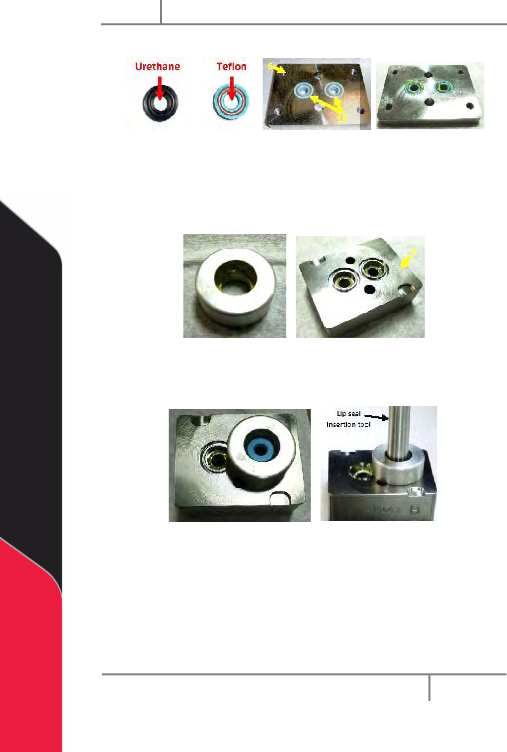
10. Apply silicone grease to the lip seals top surfaces.
Figure 35: Lip Seals in Seal Plate
11. Apply a small amount of grease inside the alignment tool and the lip seal
openings on the fluid section.
12. Put a lip seal in the lip seal alignment tool (supplied with tool kit) and put it on
the top of the fluid section. Install the flared side into the fluid section first.
Figure 36: Lip Seal Alignment Tool and Fluid Section
13. Put the lip seal insertion tool onto the top of the lip seal and use it to push the
seal into the fluid section so it is flush with the surface.
Figure 37: Lip Seal Insertion Tool
14. Do steps 11-13 again for the last lip seal.
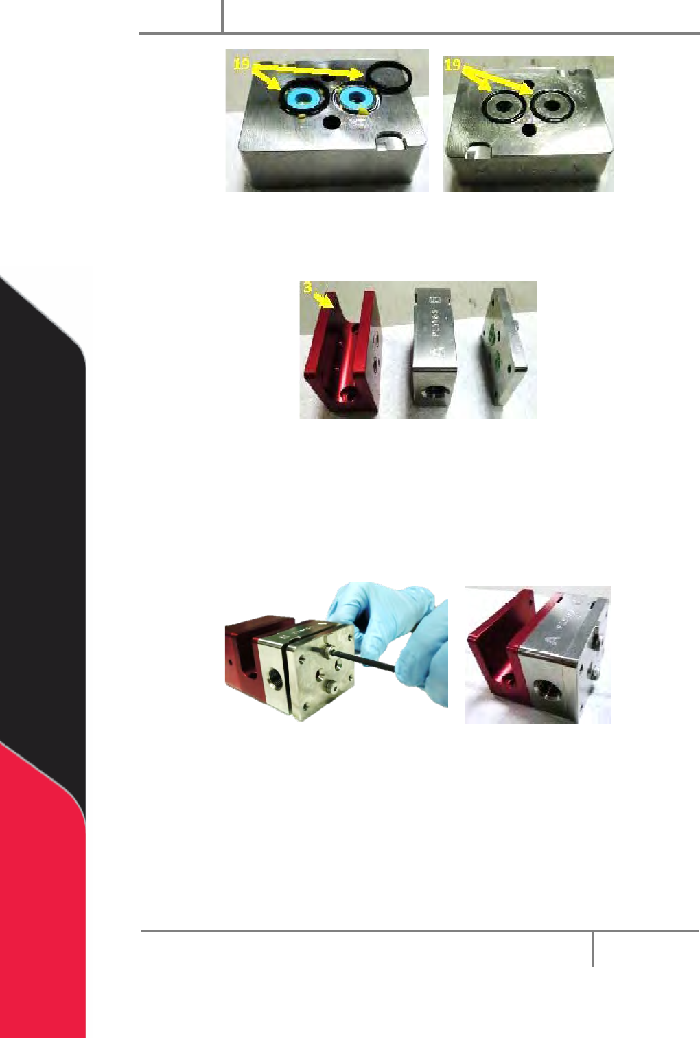
15. Apply silicone grease to four 016 O-rings and put one in each of the grooves of
the fluid section on both sides of the block.
PC200
PVA
Revision G (2019)
26 of 56
Figure 38: O-rings for the Fluid Section
16. Align the separation block, the fluid body and the seal plate. Make sure the
sections point the correct way (as shown).
Figure 39: Align the Sections
17. Use a hex key to install two #10-24 shoulder bolts at the seal plate to attach the
assembly. Tighten the first bolt 1-2 turns and then the second bolt 1-2 turns.
Repeat this procedure until the bolts are fully engaged.
NOTE: When bolts are tightened in small increments of 1-2 turns, the lip seals stay
correctly positioned.
Figure 40: Assemble the Separation Block, Fluid Body and Seal Plate
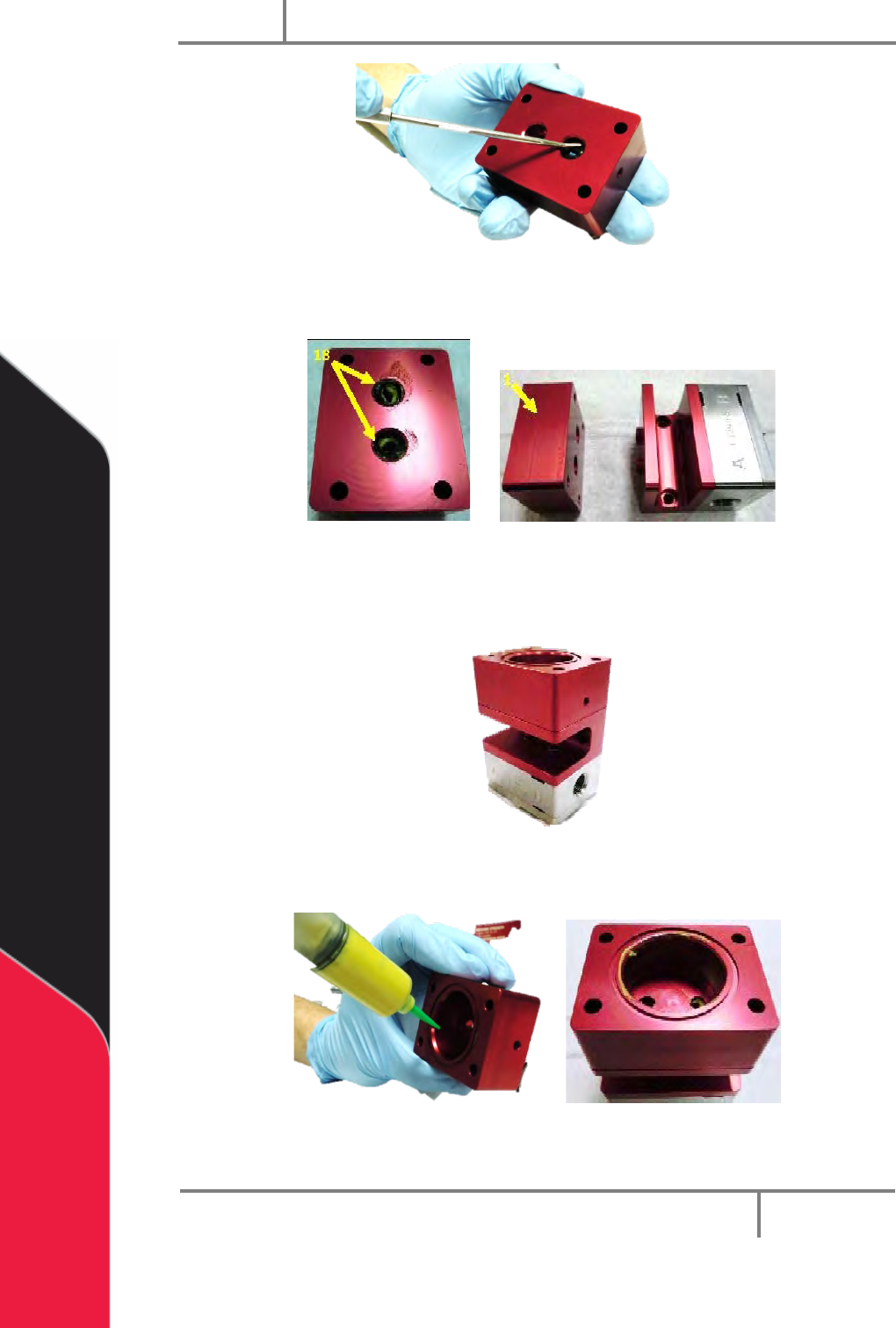
18. Apply silicone grease to two 108 Buna O-rings and put them in the bottom
openings of the air cylinder.
19. Use a pick to make sure the O-rings are correctly aligned and installed.
PC200
PVA
Revision G (2019)
27 of 56
Figure 41: Align the O-rings
20. Align the air cylinder and the assembly.
Figure 42: Air Cylinder Openings Aligned with the Assembly
21. Put the air cylinder on the fluid assembly. Make sure the air port is on the
right side.
Figure 43: Air Cylinder and Fluid Assembly
22. Apply silicone grease to the cylinder wall.
Figure 44: Apply Grease to the Cylinder Wall
23. Apply silicone grease to the O-ring on the piston-rod assembly.