PC200_Manual_REV_G-1.pdf - 第24页
PC200 PVA Revis ion G (201 9) 24 of 56 Fig ure 32 : Tighten Rods NOTE: Make sure the rods are tight and cannot turn freely by hand. 6. Put the 123 Bu na O - ring on the pis ton . Fig ure 33 : Put the O - ri ng on the P i…
PC200
PVA
Revision G (2019)
23 of 56
Assemble the Valve
This section shows how to assemble PC200 series valves (Standard PC200R process
is shown).
Some installation steps that involve rods, lip seals, sleeve bearings, and O-rings will
differ between the R and RW series of the PC200. Not all options are shown. Valve
series are closely related. When procedures are different from what is shown, “Notes”
are given. If you have questions about procedure steps, parts, or content, contact PVA’s
customer service department.
Procedure
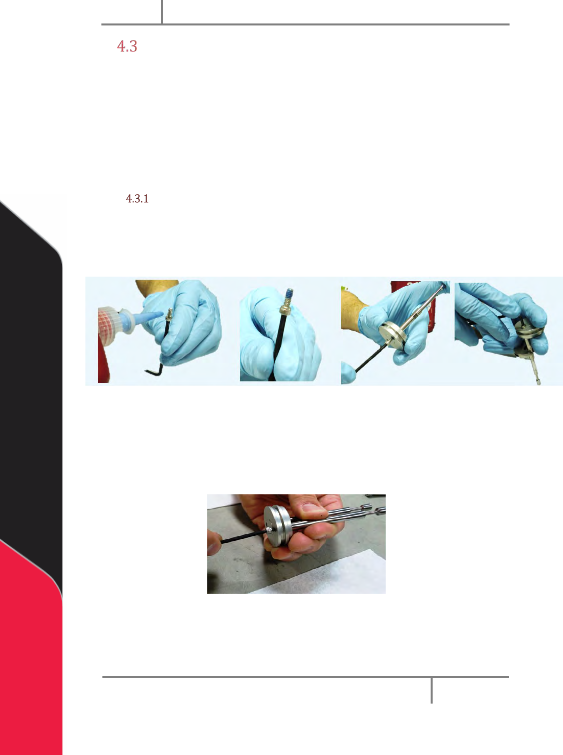
1. Apply removable thread lock to a machine screw.
2. Put the screw with thread lock in the piston.
3. Put a rod in into the countersunk side of the piston.
Figure 30: Install Screw in the Piston-Rod Assembly
4. Use a 3/16” wrench (or an adjustable wrench) on the flats of each rod to hold
them in place and tighten the screw with a 7/64” hex key. The screw will
engage the rod.
5. Repeat steps 1-4 for the second rod and machine screw.
Figure 31: Rods and Piston
NOTE: RW-series PC200 uses two different size rods.
PC200
PVA
Revision G (2019)
24 of 56
Figure 32: Tighten Rods
NOTE: Make sure the rods are tight and cannot turn freely by hand.
6. Put the 123 Buna O-ring on the piston.
Figure 33: Put the O-ring on the Piston
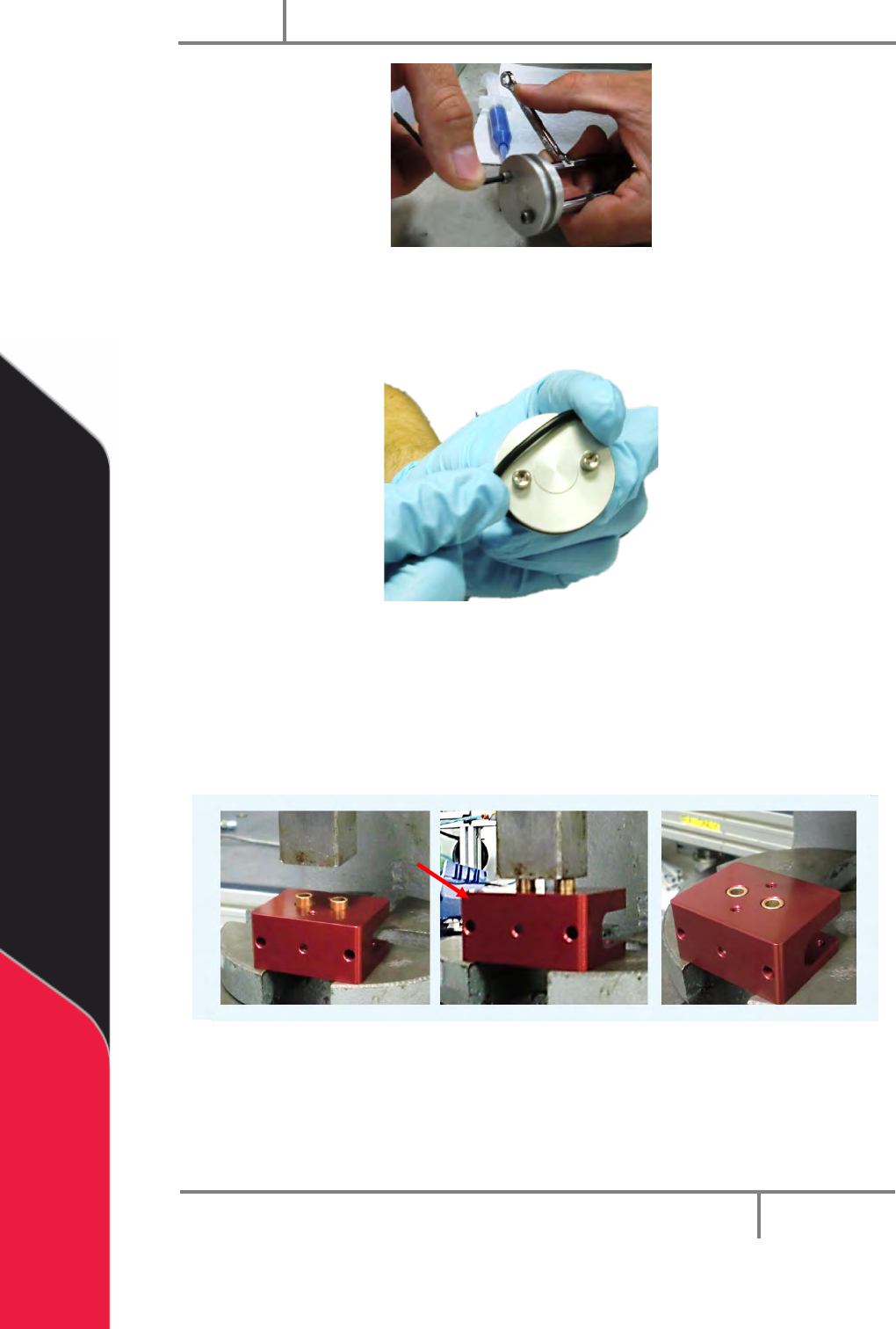
7. Align the sleeve bearings with the two holes in the top of the separation
block.
8. Use a press to push the sleeve bearings into the bottom holes of the
separation block until they are flush with the bottom of the block.
Figure 34: Sleeve Bearings Installed in the Separation Block
Note: RW-series PC200 uses two different size sleeve bearings.
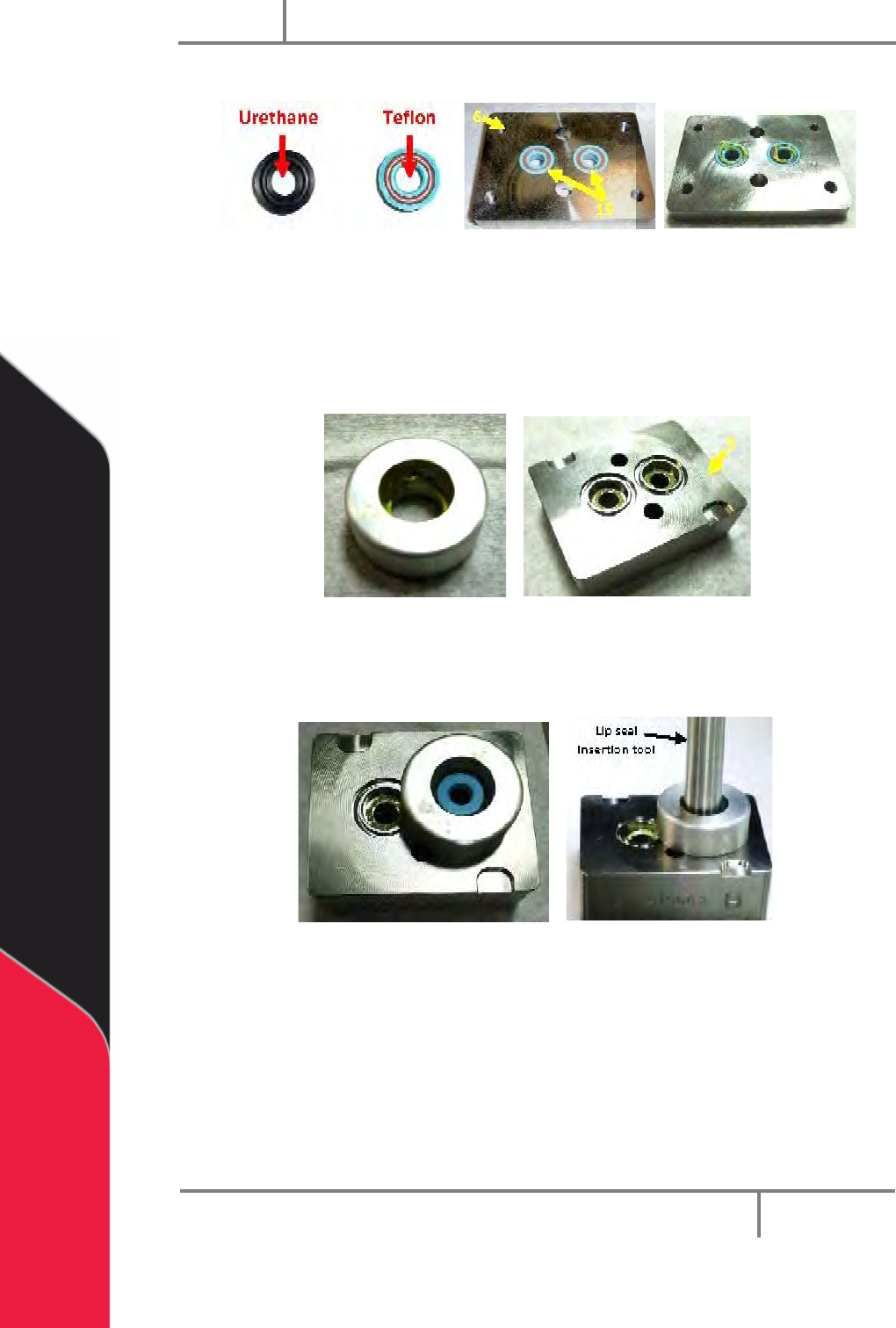
9. Use your hands to push two lip seals (Teflon® seals shown), O-ring side up,
into the seal plate holes. Do not to damage them.
17
PC200
PVA
Revision G (2019)
25 of 56
10. Apply silicone grease to the lip seals top surfaces.
Figure 35: Lip Seals in Seal Plate
11. Apply a small amount of grease inside the alignment tool and the lip seal
openings on the fluid section.
12. Put a lip seal in the lip seal alignment tool (supplied with tool kit) and put it on
the top of the fluid section. Install the flared side into the fluid section first.
Figure 36: Lip Seal Alignment Tool and Fluid Section
13. Put the lip seal insertion tool onto the top of the lip seal and use it to push the
seal into the fluid section so it is flush with the surface.
Figure 37: Lip Seal Insertion Tool
14. Do steps 11-13 again for the last lip seal.
15. Apply silicone grease to four 016 O-rings and put one in each of the grooves of
the fluid section on both sides of the block.