PC200_Manual_REV_G-1.pdf - 第9页
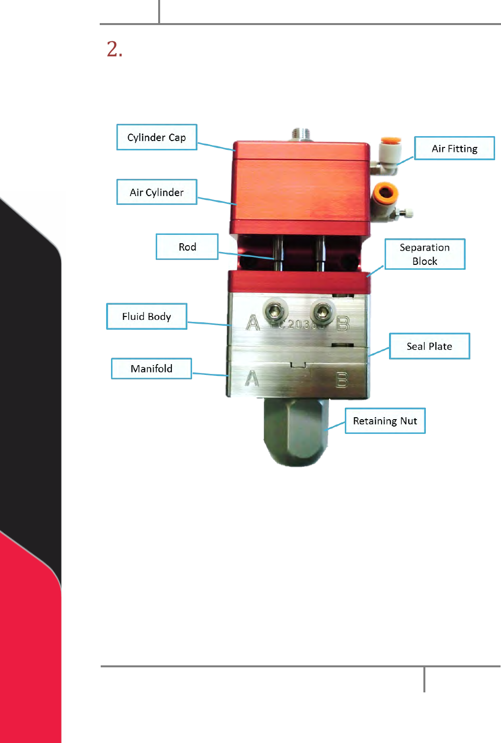
PC200 PVA Revis ion G (201 9) 9 of 56 Overview Befo re you operate th e valve, kn ow the valve compon ents. Examine the val v e compo nents shown be low for safe and corr ect operat ion. Fig ure 2 : Valv e Components
PC200
PVA
Revision G (2019)
8 of 56
Personal Protective Equipment
Operators must use eye protection because material contents are under pressure.
Always wear gloves when handling materials and solvents. Refer to MSDS sheets on the
material being dispensed for other precautions.
Waste Disposal
Dispose of all used parts and materials in accordance with local laws and regulations.
Tool Kit
PVA offers tool kits for dispense valves. The tool kit for the PC200 series valve is part
number B12-2602. This includes all necessary tools and lubricant to do maintenance on
this valve.
Table 1: B12-2602 Contents List
Qty
Part Number
Description
1
0266244
8” Adjustable Wrench
1
7122A47
3/16” Hex Key
2
26571
5/32” Hex Key
2
7122A44
1/8” Hex Key
2
7122A43
7/64” Hex Key
1
56945A13
3/16” Combination Wrench
1
B62-2048
2.5cc Silicone Lubricant
1
MM115
Removable Thread Locker
1
5516A18
Tweezers
1
9570K71
Hook and Pick Set
1
214-0544
Lip Seal Alignment Tool
1
98381A636
Lip Seal Insertion Tool
1
8511T17
Tool Bag
PC200
PVA
Revision G (2019)
9 of 56
Overview
Before you operate the valve, know the valve components. Examine the valve
components shown below for safe and correct operation.
Figure 2: Valve Components
PC200
PVA
Revision G (2019)
10 of 56
Valve Operation
Startup
1. Install the valve pneumatically as shown in Section 1.5 and set the air
pressure that operates the valve between 60-100 psi.
2. Cycle the valve several times. Make sure that the valve is not pointed at
anyone.
When the valve cycles correctly, you can hear the piston hit the stroke adjustment
screw and the rods can be seen going up and down in the center.
NOTE: If the valve does not cycle correctly, refer to Section 11.
3. Connect the material delivery system to the valve. Part A material
connects on the on the left side, part B material connects on the right side.
4. Cycle the valve open to bleed. Part A and B materials should start to
flow separately out of the fluid manifold.
5. Bleed the valve until all the air is released, and the material releases
smoothly without any breaks in the flow. Any break in the flow of the
material shows there is still air in the system.
6. Ble
ed air from the bleed screws if necessary.
NOTE: Part A and B materials may not start to dispense from the valve at
the same time, flow depends on the necessary mix ratio.
7. Use a 3/16” hex key to adjust the stroke adjustment screw to get the
necessary amount of snuff back.
Turn the stroke adjustment screw clockwise to decrease the amount of snuff back,
or counter-clockwise to increase the amount of snuff back. If the stroke adjustment
screw is turned down too far the valve will not close and material will leak from the
manifold nozzle.
NOTE: A good general setting for snuff back is to turn the stroke
adjustment screw clockwise until material starts to leak from the valve
manifold when under pressure, then turn the stroke adjustment screw a ½
turn counter-clockwise or until it does not leak.
8. When snuff back is set, use an adjustable wrench to tighten the jam nut
against the sealing washer and cylinder cap to lock it in place.
NOTE: Refer to Section 11 for any other problems.