PC200_Manual_REV_G-1.pdf - 第7页
PC200 PVA Revis ion G (201 9) 7 of 56 Theory o f Ope rat io n The PC200 is a rear cl osing, two component dispensin g v alve. Applications inc lude potting, bea d p lacement, and gaskets wher e a low t o medium flow r at…
PC200
PVA
Revision G (2019)
6 of 56
Safety
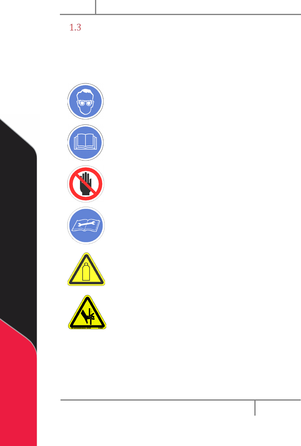
Certain warning symbols are affixed to the machine and correspond to notations in this
manual. Before operating the system, identify these warning labels and read the
notices described below. Not all labels may be used on any specific system.
Always wear approved safety glasses when you operate or
work near the workcell.
Before you operate the system, read and understand the
manuals provided with the unit.
Never put hands or tools in areas with this symbol when the
machine is in operation. A dangerous condition may exist.
Read and understand the manuals provided with the unit
before any repairs or maintenance is done. Only a qualified
individual should do service.
Use caution when there are pressurized vessels. Find and
repair any leaks immediately. Always wear appropriate safety
equipment when you work with pressurized vessels or vessels
that contain chemicals.
Shear hazard from moving parts. Avoid contact.
PC200
PVA
Revision G (2019)
7 of 56
Theory of Operation
The PC200 is a rear closing, two component dispensing valve. Applications include
potting, bead placement, and gaskets where a low to medium flow rate is required. This
valve has adjustable snuff back to prevent drips or strings at the end of the static mixer.
Part A and part B materials flow into the valve separately and out of the valve separately
into a disposable static mixer. It is not necessary to disassemble and clean the valve at
the end of each day. The PC200 has a divorced design made of two major sections: the
air section and the fluid section
Air Section
The air section is an aluminum body with a simple piston/cylinder combination used to
open and close the valve. The stroke adjustment screw in the upper air body controls
how far the piston and rod assembly can retract and controls snuff back.
Fluid Section
The fluid section is available in two materials:
• Stainless steel
• Aluminum (decreased weight for handheld applications)
The fluid section includes two rods with lip seals on each side of the valve to control
fluid flow of part A and part B. Fluid dispenses as the rods move to the forward position
past the lip seals. When the rods retract back into the lip seals the fluid flow stops and
creates a snuff back action on the fluid.
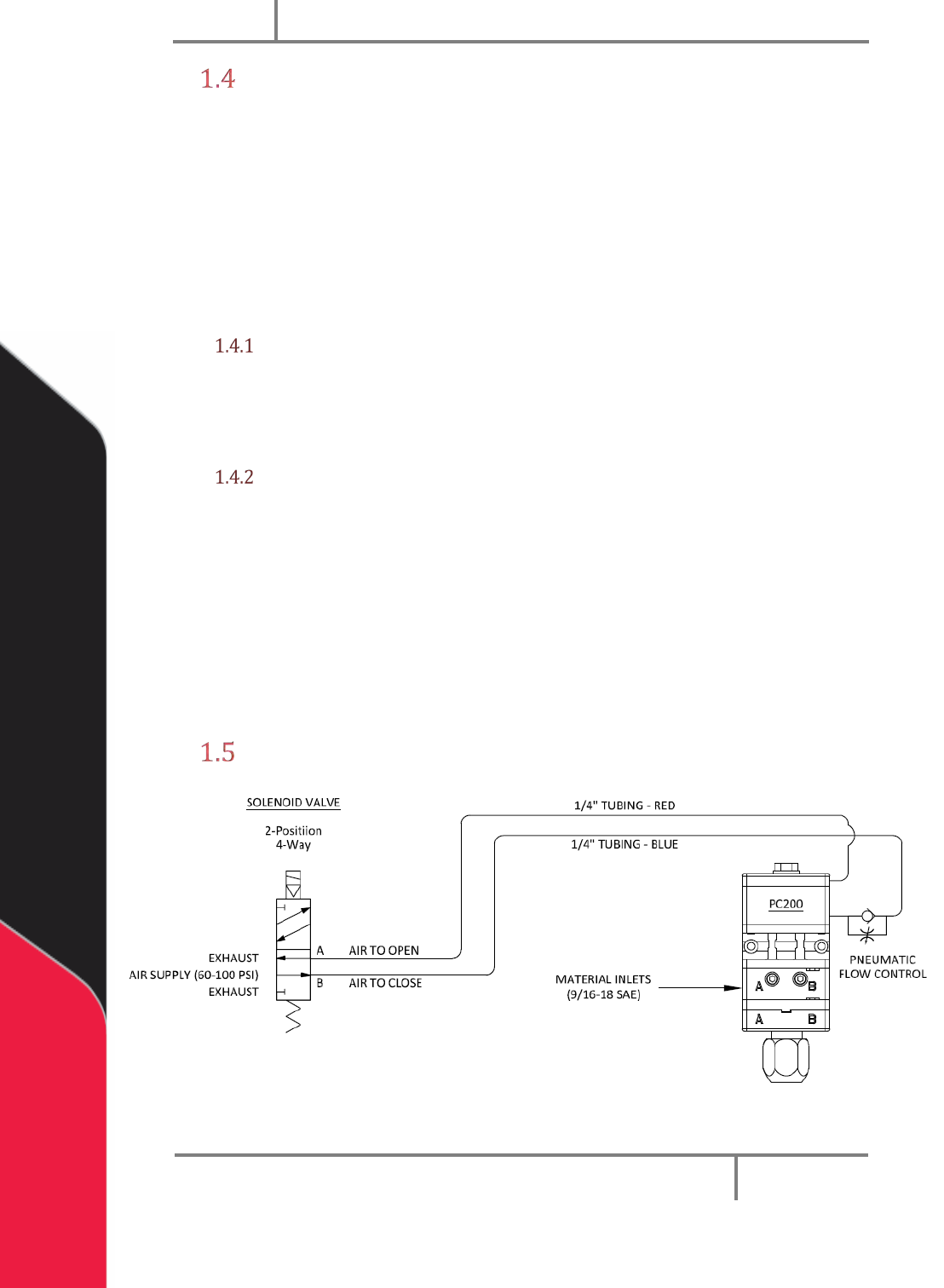
Pneumatic Schematic
Figure 1: General PC200 Pneumatic Schematic
PC200
PVA
Revision G (2019)
8 of 56
Personal Protective Equipment
Operators must use eye protection because material contents are under pressure.
Always wear gloves when handling materials and solvents. Refer to MSDS sheets on the
material being dispensed for other precautions.
Waste Disposal
Dispose of all used parts and materials in accordance with local laws and regulations.
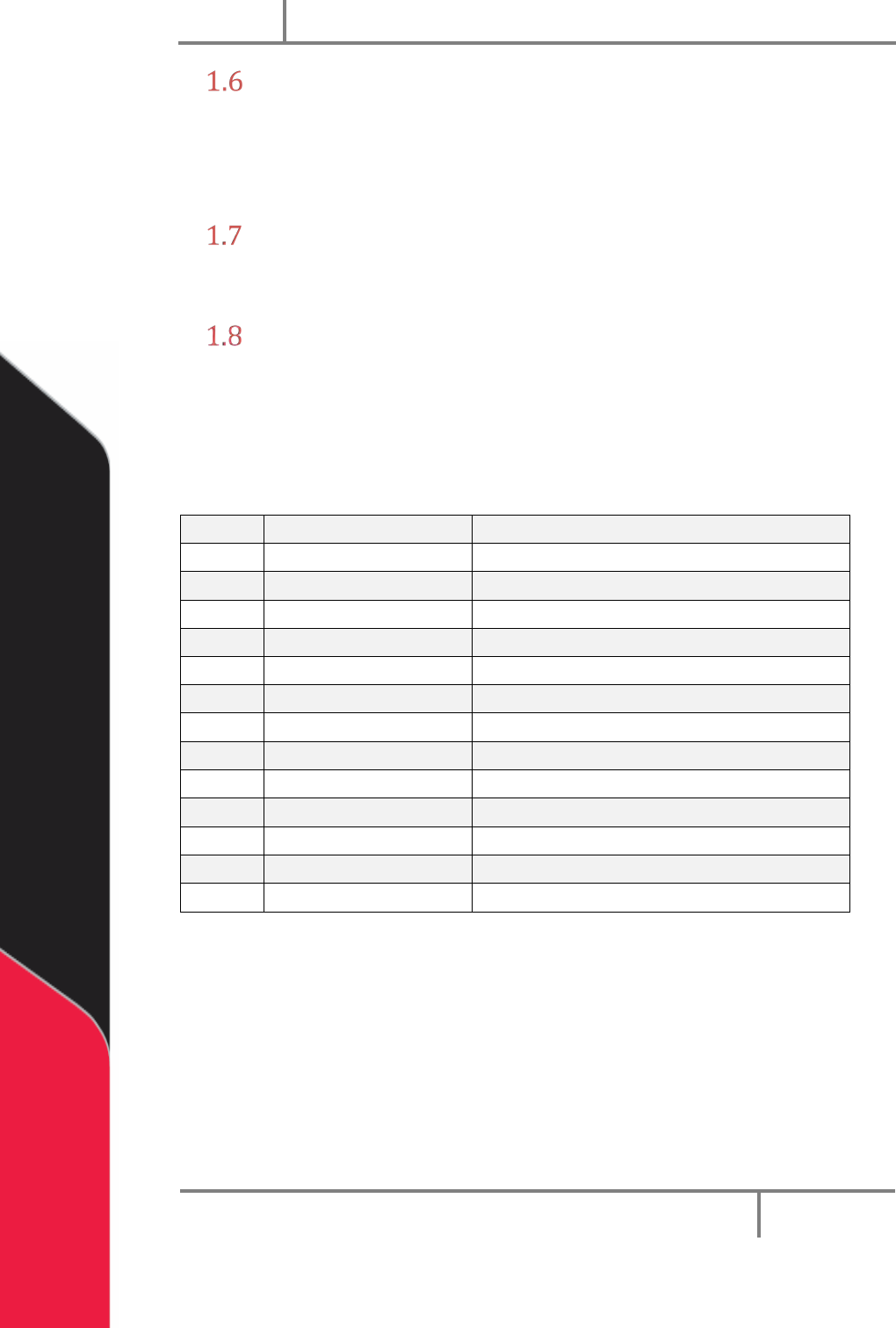
Tool Kit
PVA offers tool kits for dispense valves. The tool kit for the PC200 series valve is part
number B12-2602. This includes all necessary tools and lubricant to do maintenance on
this valve.
Table 1: B12-2602 Contents List
Qty
Part Number
Description
1
0266244
8” Adjustable Wrench
1
7122A47
3/16” Hex Key
2
26571
5/32” Hex Key
2
7122A44
1/8” Hex Key
2
7122A43
7/64” Hex Key
1
56945A13
3/16” Combination Wrench
1
B62-2048
2.5cc Silicone Lubricant
1
MM115
Removable Thread Locker
1
5516A18
Tweezers
1
9570K71
Hook and Pick Set
1
214-0544
Lip Seal Alignment Tool
1
98381A636
Lip Seal Insertion Tool
1
8511T17
Tool Bag