754_____cmeng0000.pdf - 第11页
Documenting Process Calibrator Symbols 3 • Connect the common test lead before the live test lead and remove the live test lead before the common test lead. • Use only current probes, test leads, and adapters supplied wi…

753/754
Calibration Manual
2
Safety Information
A Warning identifies condition and procedures that are dangerous to the user. A Caution
identifies conditions and procedures that can cause damage to the Product or the
equipment under test.
XW Warning
To prevent personal injury, use the Product only as
specified, or the protection supplied by the Product can be
compromised.
To prevent possible electrical shock, fire, or personal injury:
• Read all safety Information before you use the
Product.
• Carefully read all instructions.
• Use only correct measurement category (CAT),
voltage, and amperage rated probes, test leads, and
adapters for the measurement.
• The battery must be locked in place before you
operate the Product.
• Recharge the battery when the low battery indicator
shows to prevent incorrect measurements.
• Do not apply more than the rated voltage, between the
terminals or between each terminal and earth ground.
• Limit operation to the specified measurement
category, voltage, or amperage ratings.
• Do not exceed the Measurement Category (CAT)
rating of the lowest rated individual component of a
Product, probe, or accessory.
• Measure a known voltage first to make sure that the
Product operates correctly.
• Do not touch voltages > 30 V ac rms, 42 V ac peak, or
60 V dc.
• Do not use the Product around explosive gas, vapor,
or in damp or wet environments.
• Do not use, and disable the Product if it is damaged.
• Do not use the Product if it operates incorrectly.
• Keep fingers behind the finger guards on the probes.
• Remove all probes, test leads, and accessories that
are not necessary for the measurement.
• Only use probes, test leads, and accessories that
have the same measurement category, voltage, and
amperage ratings as the Product.
Documenting Process Calibrator
Symbols
3
• Connect the common test lead before the live test
lead and remove the live test lead before the common
test lead.
• Use only current probes, test leads, and adapters
supplied with the Product.
• Do not touch the probes to a voltage source when the
test leads are connected to the current terminals.
• Use only cables with correct voltage ratings.
• Do not use test leads if they are damaged. Examine
the test leads for damaged insulation, exposed metal,
or if the wear indicator shows. Check test lead
continuity.
• Examine the case before you use the Product. Look
for cracks or missing plastic. Carefully look at the
insulation around the terminals.
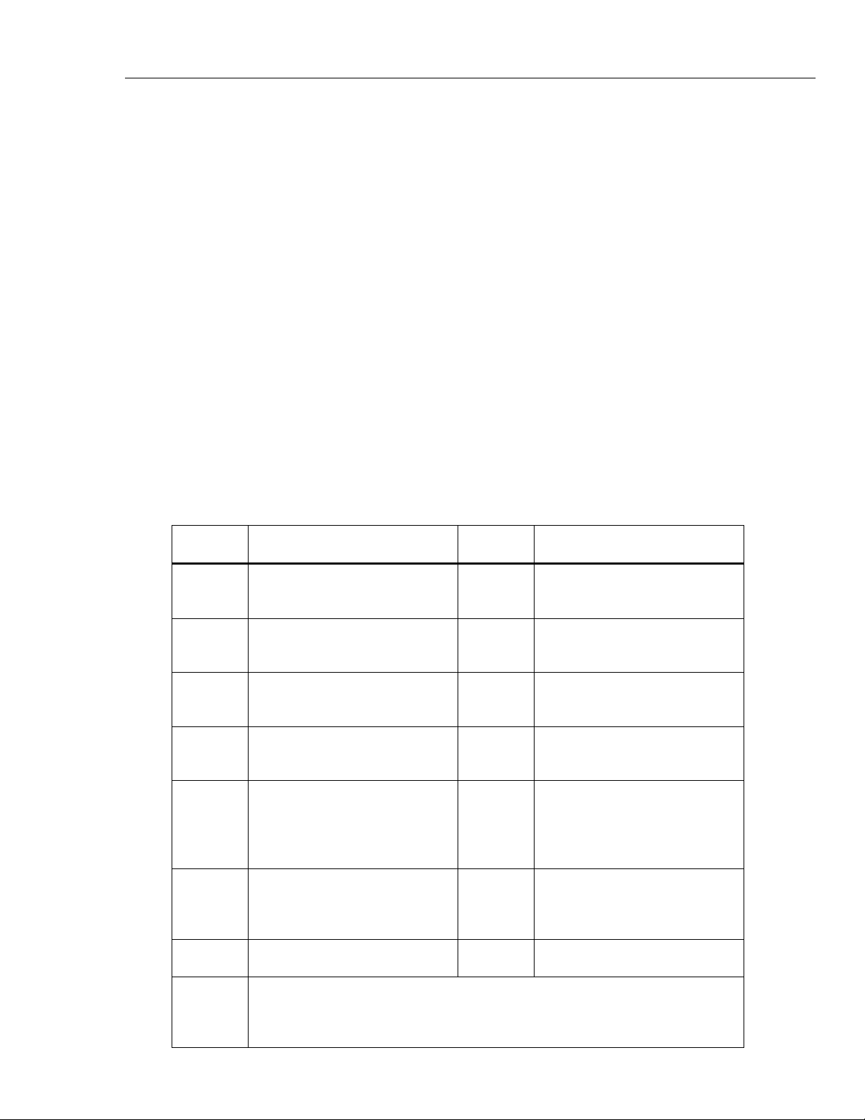
Symbols
Symbols used on the Product and in this manual are shown in Table 1.
Table 1. Symbols
Symbol Meaning Symbol Meaning
J Earth ground ˜
Common (LO) Input
equipotentiality
AC- alternating current
)
Conforms to relevant North
American Safety Standards.
DC- direct current P
Conforms to European Union
directives.
W
Risk of danger. Important
information. See manual.
f
Pressure
X
Hazardous voltage. Risk of
electrical shock.
~
Do not dispose of this product as
unsorted municipal waste. Go to
Fluke’s website for recycling
information.
,
Application around and removal
from HAZARDOUS LIVE
conductors is permitted.
Conforms to relevant Australian
standards.
T Double insulated ® German certifying body.
CAT II
CAT II equipment is designed to protect against transients from energy-consuming
equipment supplied from the fixed installation, such as TVs, PCs, portable tools, and
other household appliances.
753/754
Calibration Manual
4
Specifications
General Specifications
All specifications apply from +18 °C to +28 °C unless stated otherwise.
All specifications assume a 5-minute warmup period.
Measurement specifications are valid only when Damping is turned on. When damping is turned off, or when the
gannunciator is shown, floor specifications are multiplied by 3. Floor specifications are the second part of the
specifications. The measure pressure, temperature, and frequency functions are specified only with damping on.
Specifications are valid to 110 % of range. The following exceptions are valid to 100 % of range: 300 V dc, 300 V ac,
22 mA source and simulate, 15 V dc source, and temperature measure and source.
To achieve the best noise rejection, use battery power.
Size (H x W x L) ..................................................................... Height = 63.35 mm (2.49 inches) x Width =
136.37 mm (5.37 inches) x Length = 244.96 mm
(9.65 inches)
Weight .................................................................................... 1.23 kg (2.71 lb) (Batteries included)
Display ................................................................................... 480 by 272 pixel graphic LCD, 95 x 54 mm
Power ..................................................................................... Internal battery pack: Lithium Ion, 7.2 V dc, 30 Wh
Environmental Specifications
Operating Altitude ................................................................. 3000 m (9842 ft)
Storage Altitude .................................................................... 13000 m (42650 ft)
Operating Temperature ........................................................ -10 to 50 °C
Storage Temperature ........................................................... -20 to 60 °C
Relative Humidity (Maximum, non-condensing) ................ 90 % to 35 °C
75 % to 40 °C
45 % to 50 °C
Standards and Agency Approval Specifications
Protection Class .................................................................... Pollution Degree II IP 52
Double Insulation Creepage and Clearance ....................... Per IEC 61010-1
Installation Category ............................................................ 300 V CAT II
Design Standards and Compliance .................................... EN/IEC 61010-1:2010, CAN/CSA C22.2 No. 61010-1-04,
ANSI/UL 61010-1:2004
EMI, RFI, EMC ........................................................................ EN 61326-1:2006
RF Fields ................................................................................ Accuracy for all functions is not specified in RF fields >3 V/m
Detailed Specifications
Specifications valid after a 5-minute warmup.
Specifications are valid to 110 % of Range with the following exceptions: 300 V dc measure, 300 V ac measure, 50 kHz
measure and source, 22 mA source and simulate, 15 V dc source, and temperature measure and source which are valid
to 100 % of range.
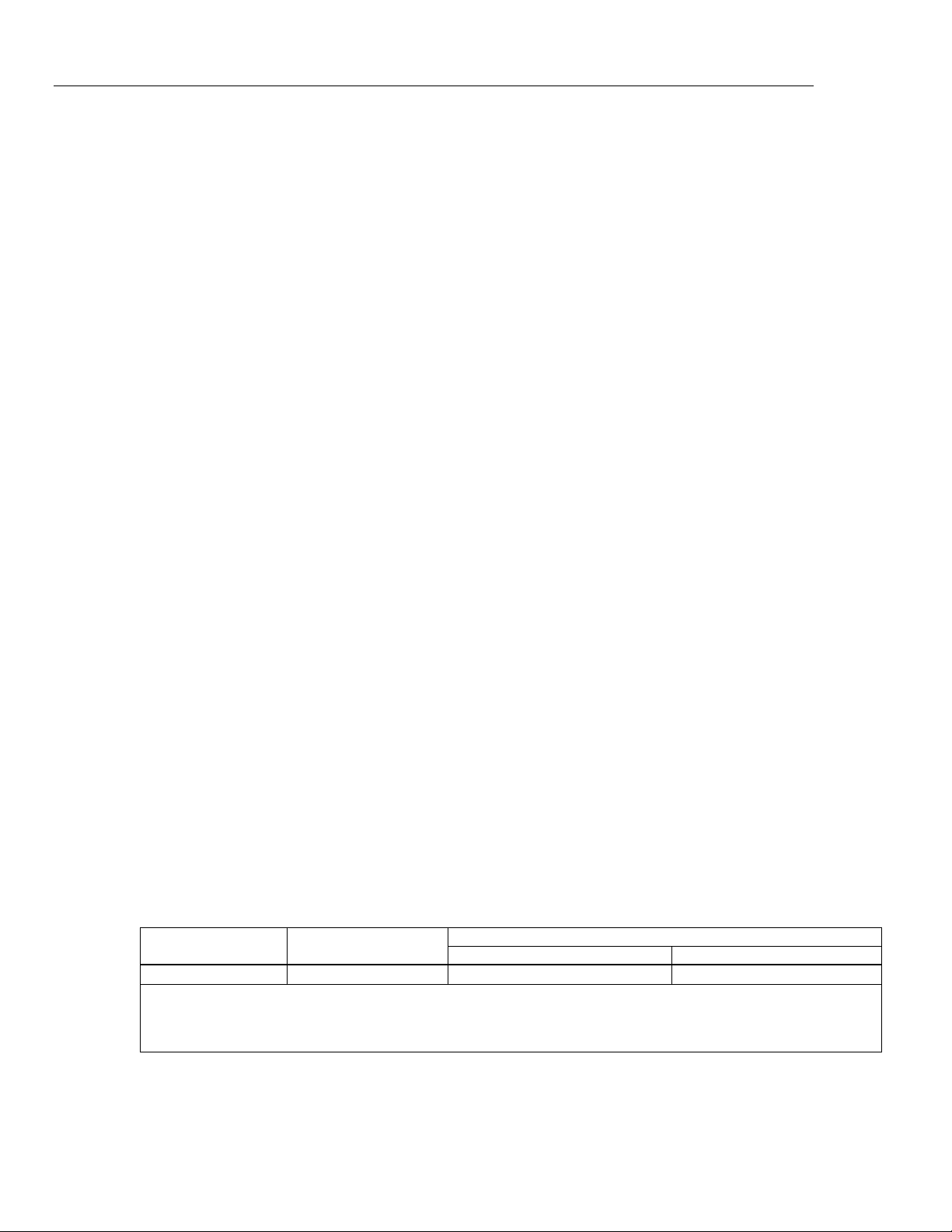
DC mV Measurement
Range Resolution
% of Reading + Floor
1-Year 2 Year
±100.000 mV
0.001 mV 0.02 % + 0.005 mV 0.03 % + 0.005 mV
Input Impedance: >5 MΩ
Maximum Input Voltage: 300 V, IEC 61010 300 V CAT II
Temperature coefficient: (0.001 % of reading + 0.001% of range) / °C (<18 °C or >28 °C)
Normal mode rejection: >100 dB at 50 or 60 Hz nominal