754_____cmeng0000.pdf - 第23页
Documenting Process Calibrator Performance Verification Tests 15 5522A CALIBRATOR Fl u ke 75X Fl u ke 5522A 2-WIRE COMP ON gso05.eps Figure 3. Resistance Measu reme nt Verification Connections Table 6. Resistance Measure…
753/754
Calibration Manual
14
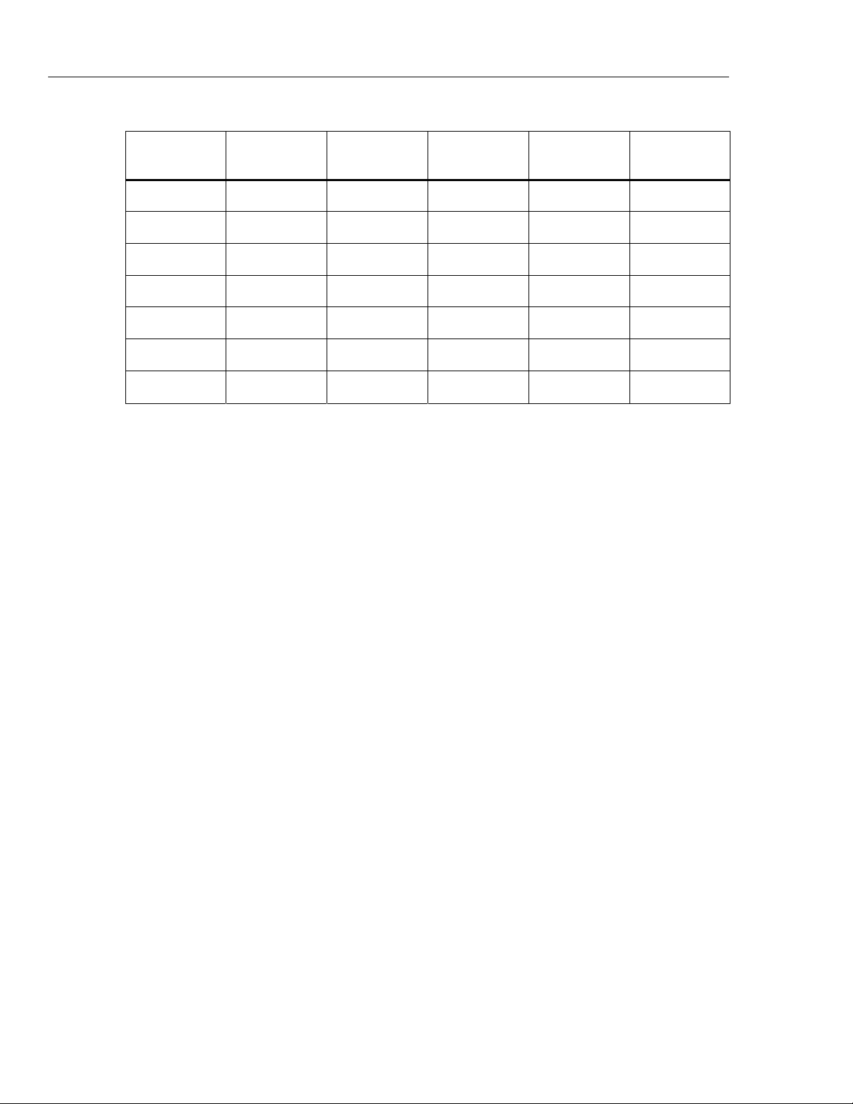
Table 5. DC Current Measurement Verification Points
UUT Range Input mA
Minimum
1-Yea
r
Maximum
1-Yea
r
Minimum
2-Yea
r
Maximum
2-Yea
r
30 mA 4 mA 3.995 4.005 3.992 4.008
30 mA 20 mA 19.993 20.007 19.990 20.010
30 mA 30 mA 29.992 30.008 29.989 30.012
30 mA -30 mA -30.008 -29.992 -30.012 -29.989
100 mA 0 mA -0.02 0.02 -0.03 0.03
100 mA 100 mA 99.97 100.03 99.96 100.04
100 mA -100 mA -100.03 -99.97 -100.04 -99.96
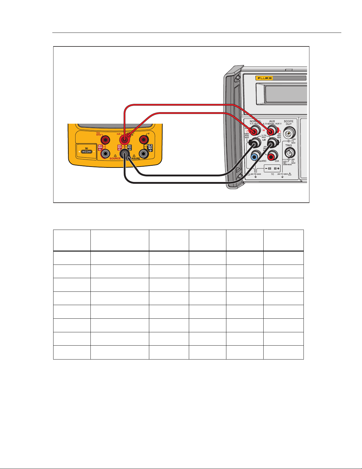
Resistance Measurement
To verify the resistance measurement function:
1. Connect the UUT to the 5522A as shown in Figure 3.
2. Use a four-wire connection at the 5522A, transitioning to two wires at the UUT,
and turn on Two-Wire Compensation.
3. Set the UUT to the resistance measurement function.
4. Push the Range softkey on the UUT to lock on the 10 Ω range.
5. Set the 5522A to the first test point in Table 6.
6. See if the value shown on the UUT is in the range shown in the applicable
column.
7. Continue through the test points. Make sure to lock the UUT on the specified
range.
8. When you complete the test, set the 5522A to STANDBY.
Documenting Process Calibrator
Performance Verification Tests
15
5522A
CALIBRATOR
Fluke 75X
Fluke 5522A
2-WIRE COMP ON
gso05.eps
Figure 3. Resistance Measurement Verification Connections
Table 6. Resistance Measurement Verification Points
UUT
Range
Input
Minimum
1-Year
Maximum
1-Year
Minimum
2-Year
Maximum
2-Year
10.000 Ω 0 Ω -0.050 0.050 -0.070 0.070
10.000 Ω 10 Ω 9.945 10.055 9.923 10.077
100.00 Ω 0 Ω -0.05 0.05 -0.07 0.07
100.00 Ω 100 Ω 99.90 100.10 99.86 100.14
1000.0 Ω 0 Ω -0.5 0.5 -0.7 0.7
1000.0 Ω 1 kΩ 999.0 1001.0 998.6 1001.4
10.000 kΩ 0 Ω -0.010 0.010 -0.015 0.015
10.000 kΩ 10 kΩ 9.980 10.020 9.970 10.030
753/754
Calibration Manual
16
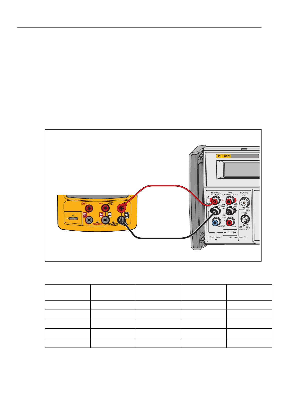
Frequency Measurement
To verify the frequency measurement function:
1. Connect the UUT as shown in Figure 4 .
2. Set the UUT to the frequency measurement function.
3. Select the <20 Hz range for the first step. Use the ≥20 Hz range thereafter.
4. Set the 5522A to the first test point in Table 7.
5. See if the frequency value shown on the UUT is in the range shown in the
applicable column.
6. Continue through the test points.
7. When you complete the test, set the 5522A to STANDBY.
5522A
CALIBRATOR
Fluke 75X
Fluke 5522A
gso06.eps
Figure 4. Frequency Measurement Verification Connections
Table 7. Frequency Measurement Verification Points
UUT Range Frequency Input V RMS
Minimum
1- & 2-Year
Maximum
1- & 2-Year
<20 Hz 10 Hz 300 mV 9.95 10.05
>20 Hz 150 Hz 300 mV 149.5 150.5
>20 Hz 1.2 kHz 1.0 V 1.195 1.205
>20 Hz 12 kHz 1.0 V 11.95 12.05
>20 Hz 49 kHz 2.0 V 48.95 49.05