754_____cmeng0000.pdf - 第21页
Documenting Process Calibrator Performance Verification Tests 13 DC Current Measurement To verify the dc current measurement function: 1. Connect the UUT to the 5522A and the 8508A as shown in Figure 2. 2. Disconnect the…
753/754
Calibration Manual
12
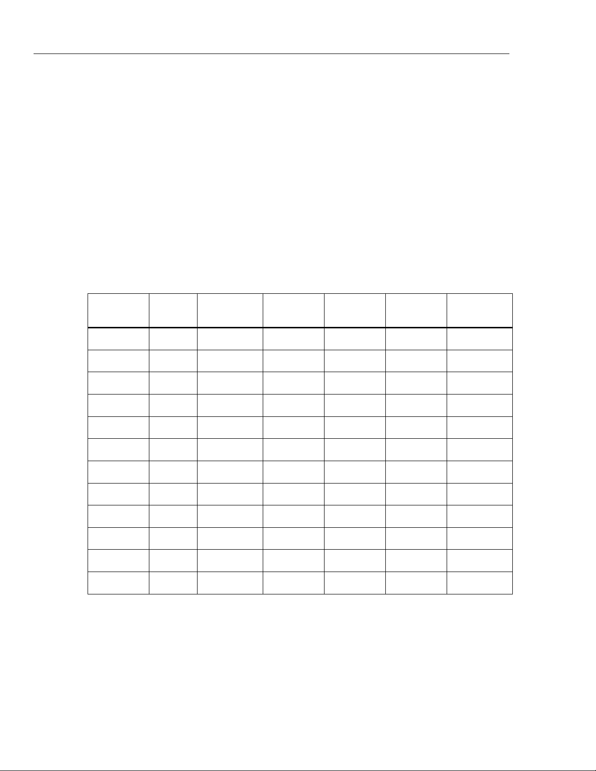
AC Volts Measurement
To verify the ac volts measurement function:
1. Connect the UUT to the 5522A as shown in Figure 1.
2. Set the UUT to the ac volts measurement function.
3. Push the Range softkey on the UUT to lock on the 3.0 V range.
4. Set the 5522A to the first test point in Table 4.
5. Stop to let the output become stable.
6. See if the value shown on the UUT is in the range shown in the applicable
column.
7. Continue through the test points. Make sure to lock the UUT on the specified
range.
8. When you complete the test, set the 5522A to STANDBY.
Table 4. AC Volts Measurement Verification Points
UUT
Ran
g
e
Input
(
RMS
)
Frequency
Minimum
1-Yea
r
Maximum
1-Yea
r
Minimum
2-Yea
r
Maximum
2-Yea
r
3.000 V 0.26 500 Hz 0.257 0.263 0.253 0.267
3.000 V 3 500 Hz 2.983 3.017 2.966 3.034
3.000 V 0.26 40 Hz 0.257 0.263 0.253 0.267
3.000 V 3 40 Hz 2.983 3.017 2.966 3.034
30.00 V 2.6 500 Hz 2.567 2.633 2.53 2.67
30.00 V 30 500 Hz 29.830 30.170 29.66 30.34
30.00 V 2.6 40 Hz 2.567 2.633 2.53 2.67
30.00 V 30 40 Hz 29.830 30.170 29.66 30.34
300.0 V 27 500 Hz 26.665 27.335 26.5 27.5
300.0 V 295 500 Hz 293.325 296.675 291.9 298.2
300.0 V 27 40 Hz 26.665 27.335 26.5 27.5
300.0 V 295 50 Hz 293.325 296.675 291.9 298.2
Documenting Process Calibrator
Performance Verification Tests
13
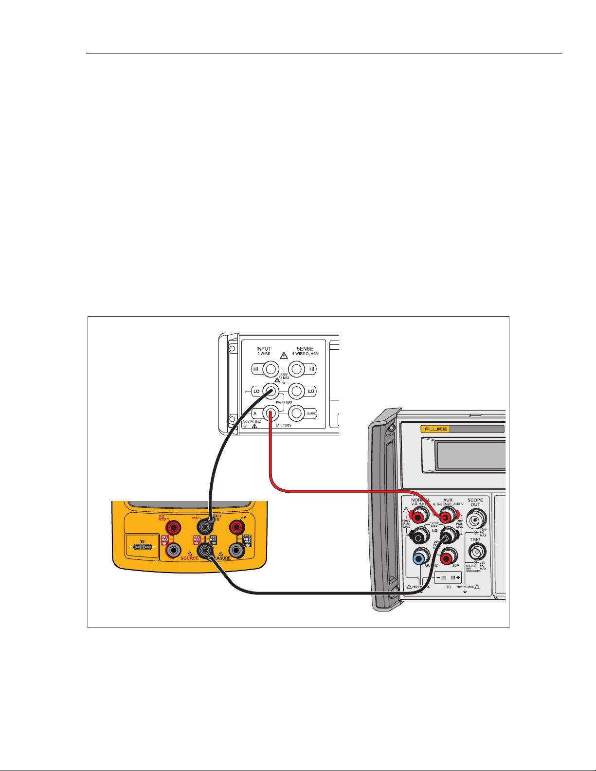
DC Current Measurement
To verify the dc current measurement function:
1. Connect the UUT to the 5522A and the 8508A as shown in Figure 2.
2. Disconnect the jumpers on the three common jacks (lows) of the UUT if they are
present.
3. Set the UUT and the 8508A to the dc current measurement function and the
5522A to source dc current.
4. Push the Range softkey on the UUT to lock on the 30 mA range.
5. Set the 5522A to the first test point in Table 5, and edit its output so that the
correct value shows on the 8508A.
6. See if the value shown on the UUT is in the range shown in the applicable
column.
7. Continue through the test points. Make sure to lock the UUT on the specified
range.
8. When you complete the test, set the 5522A to STANDBY.
5522A
CALIBRATOR
Fluke 75X
Fluke 8508A
Fluke 5522A
gso04.eps
Figure 2. DC Current Measurement Verification Connections
753/754
Calibration Manual
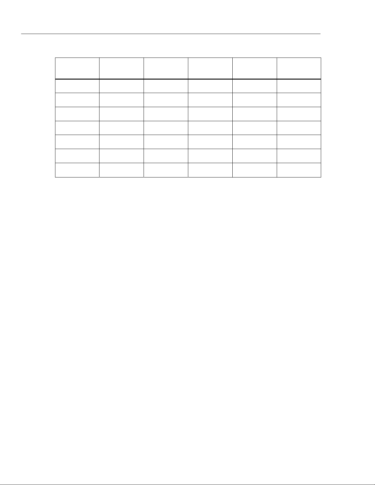
14
Table 5. DC Current Measurement Verification Points
UUT Range Input mA
Minimum
1-Yea
r
Maximum
1-Yea
r
Minimum
2-Yea
r
Maximum
2-Yea
r
30 mA 4 mA 3.995 4.005 3.992 4.008
30 mA 20 mA 19.993 20.007 19.990 20.010
30 mA 30 mA 29.992 30.008 29.989 30.012
30 mA -30 mA -30.008 -29.992 -30.012 -29.989
100 mA 0 mA -0.02 0.02 -0.03 0.03
100 mA 100 mA 99.97 100.03 99.96 100.04
100 mA -100 mA -100.03 -99.97 -100.04 -99.96
Resistance Measurement
To verify the resistance measurement function:
1. Connect the UUT to the 5522A as shown in Figure 3.
2. Use a four-wire connection at the 5522A, transitioning to two wires at the UUT,
and turn on Two-Wire Compensation.
3. Set the UUT to the resistance measurement function.
4. Push the Range softkey on the UUT to lock on the 10 Ω range.
5. Set the 5522A to the first test point in Table 6.
6. See if the value shown on the UUT is in the range shown in the applicable
column.
7. Continue through the test points. Make sure to lock the UUT on the specified
range.
8. When you complete the test, set the 5522A to STANDBY.