754_____cmeng0000.pdf - 第26页
753/754 Calibration Manual 18 DC Current Source To verify the dc current source function. 1. Connect the UUT to the 8508A as shown in Figure 6. 2. Set the 8508A to DC Current. 3. Set the UUT to dc current source (not sim…
Documenting Process Calibrator
Performance Verification Tests
17
DC Volts Source
To verify the dc volts source function:
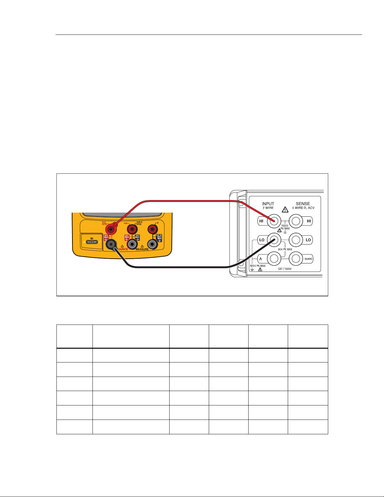
1. Connect the UUT to the 8508A as shown in Figure 5.
2. Set the 8508A to measure dc volts.
3. Set the UUT to the dc volts source function at -10 mV. Let the UUT warm up for
a minimum of 5 minutes before you read the first indication.
4. See if the value shown on the 8508A is in the range shown in the applicable
column in Table 8.
5. Continue through the test points. See if the value shown on the UUT is in the
range shown in the applicable column.
6. When you complete the test, push on the UUT two times to turn the source
function off. This conserves battery life.
Fluke 75X
Fluke 8508A
gso07.eps
Figure 5. DC Volts Source Verification Connections
Table 8. DC Volts Source Verification Points
UUT
Range
UUT Output
Minimum
1-Year
Maximum
1-Year
Minimum
2-Year
Maximum
2-Year
100.000 10 mV 9.9940 10.0060 9.9935 10.0065
100.000 0.1 V 99.9850 100.0150 99.9800 100.0200
1.00000 V 0.15 V 0.14994 0.15007 0.14993 0.15007
1.00000 V 1 V 0.99985 1.00015 0.99980 1.00020
15.0000 V 1.5 V 1.49935 1.50065 1.49928 1.50073
15.0000 V 10 V 9.99850 10.00150 9.99800 10.00200
753/754
Calibration Manual
18
DC Current Source
To verify the dc current source function.
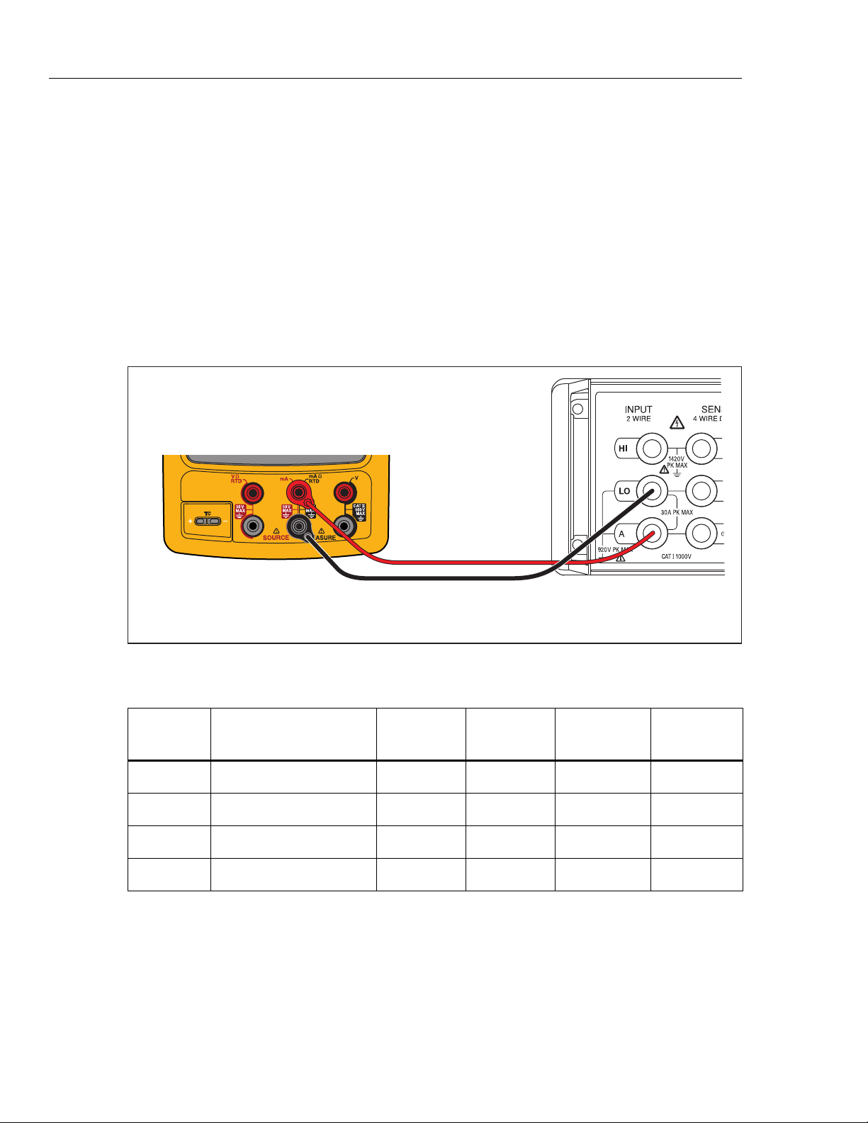
1. Connect the UUT to the 8508A as shown in Figure 6.
2. Set the 8508A to DC Current.
3. Set the UUT to dc current source (not simulate transmitter) function at 2 mA.
4. See if the value shown on the 8508A is in the range shown in the applicable
column in Table 9.
5. Continue through the test points. See if the value shown on the UUT is in the
range shown in the applicable column.
6. When you complete the test, push on the UUT two times to turn off the
source function. This conserves battery life.
Fluke 75X
Fluke 8508A
gso08.eps
Figure 6. DC Current Source Verification Connections
Table 9. DC Current Source Verification Points
UUT
Range
UUT Output
Minimum
1-Year
Maximum
1-Year
Minimum
2-Year
Maximum
2-Year
22.000 mA 2 mA 1.99680 2.00320 1.99660 2.00340
22.000 mA 4 mA 3.99660 4.00340 3.99620 4.00380
22.000 mA 12 mA 11.99580 12.00420 11.99460 12.00540
22.000 mA 21 mA 20.99490 21.00510 20.99280 21.00720
Documenting Process Calibrator
Performance Verification Tests
19
Simulate Transmitter Function
To verify the simulate transmitter function (accessed through dc current source function):
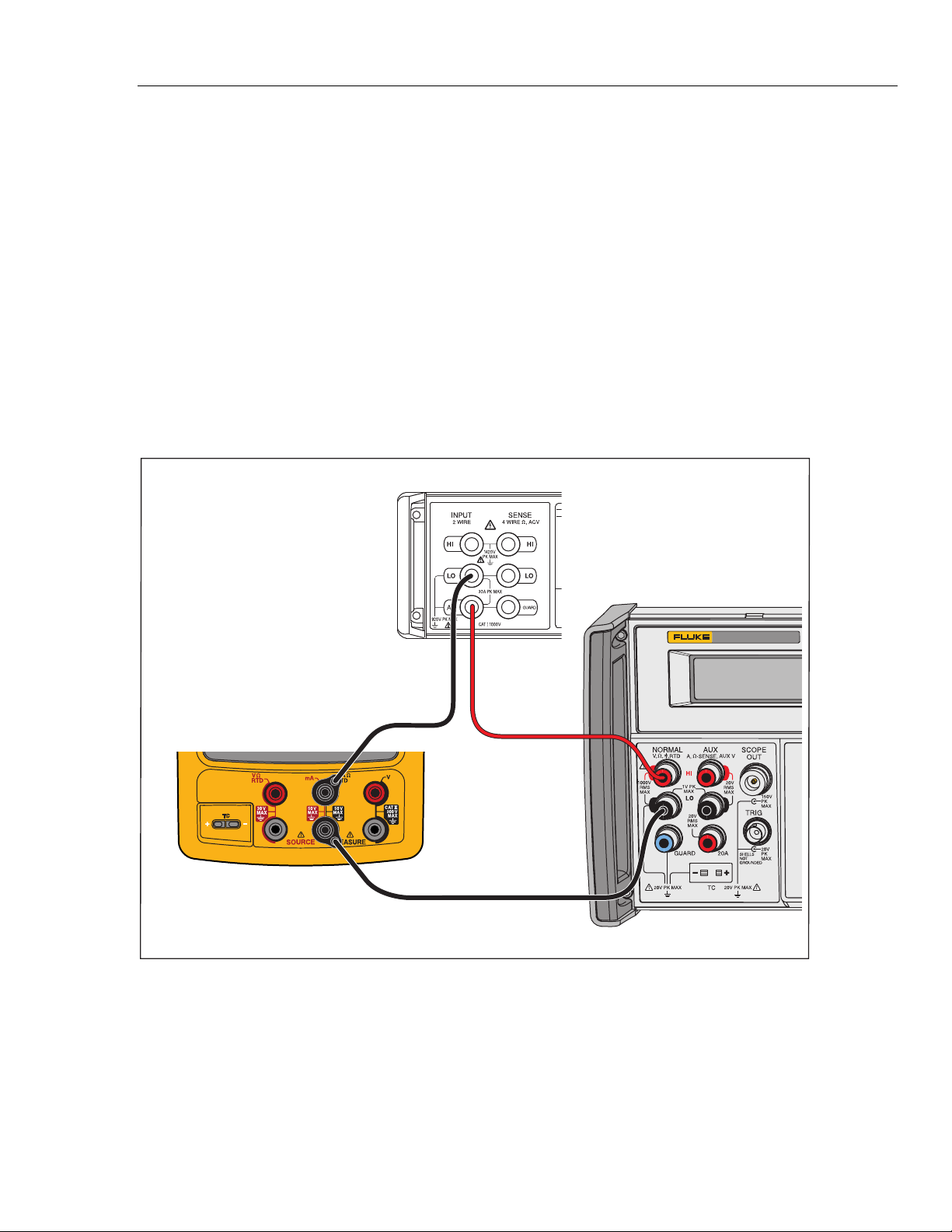
1. Connect the UUT, 8508A, and 5522A as shown in Figure 7. The 5522A is used
as a stable dc voltage source. Its value is not critical, and a different dc source
such as a battery can be used if necessary.
2. Set the 8508A to DC Current .
3. Set the UUT to the [mA Source] function and then select Simulate Transmitter.
4. Set the UUT source value to 4 mA.
5. Set the 5522A to output 8 V dc.
6. See if the value shown on the 8508A is in the range shown in Table 10.
7. Change the UUT source value to 22 mA and examine the results again in Table 10.
8. When you complete the test, set the 5522A to STANDBY and push on the
UUT two times to turn the source function off. This conserves battery life.
5522A
CALIBRATOR
Fluke 75X
Fluke 8508A
Fluke 5522A
gso09.eps
Figure 7. Simulate Transmitter Verification Connections