754_____cmeng0000.pdf - 第15页
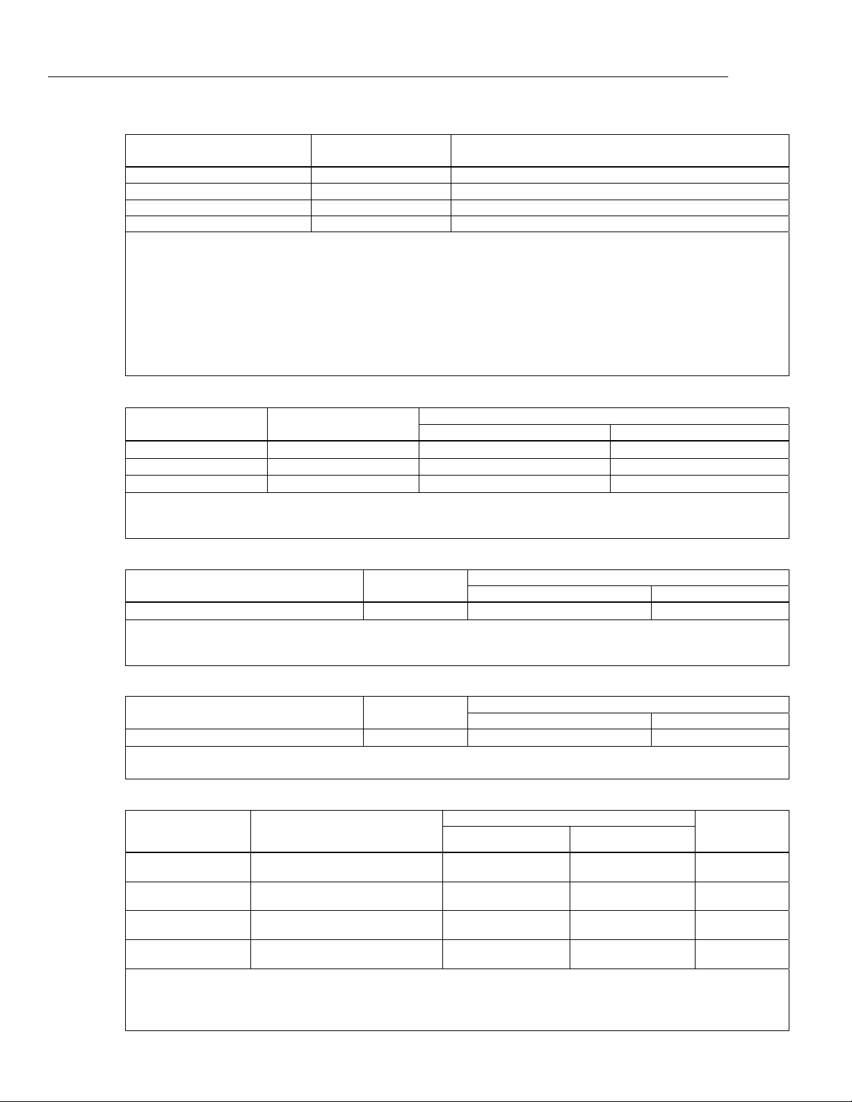
Documenting Process Calibrator Detailed Specifications 7 Frequency Sourcing Range Specification 2 Year Sine Wave: 0.1 Hz to 10.99 Hz 0.01 Hz Square Wave: 0.01 Hz to 10.99 Hz 0.01 Hz Sine and Square Wave: 11.00 Hz to 109.…
753/754
Calibration Manual
6
Frequency Measurement
Ranges Resolution 2 Year
1.00 Hz to 110.00 Hz
[1]
0.01 Hz 0.05 Hz
110.1 Hz to 1100.0 Hz 0.1 Hz 0.5 Hz
1.101 kHz to 11.000 kHz 0.001 kHz 0.005 kHz
11.01 kHz to 50.00 kHz 0.01 kHz 0.05 kHz
Coupling: AC
Minimum Amplitude for Frequency Measurement (square wave):
<1 kHz: 300 mV p-p
1 kHz to 30 kHz: 1.4 V p-p
>30 kHz: 2.8 V p-p
Maximum input:
<1 kHz: 300 V rms
>1 kHz: 30 V rms
Input Impedance: >4 MΩ
[1] For frequency measurement less than 110.00 Hz, specifications apply for signals with a slew rate >5 volt/millisecond.
±
DC Voltage Output
Range Resolution
% of Output + Floor
1-Year 2 Year
±100.000 mV 1 μV
0.01 % + 0.005 mV 0.015 % + 0.005 mV
±1.00000 V 10 μV
0.01 % + 0.00005 V 0.015 % + 0.00005 V
±15.0000 V 100 μV
0.01 % + 0.0005 V 0.015 % + 0.0005 V
Maximum Output Current: 10 mA, In the 100 mV range add 0.010 mV to specification when sourcing >1 mA.
For sourcing dc voltages <110.000 mV, accuracy is not specified in RF fields >1 V/m, 80 MHz to 700 MHz.
Temperature Coefficient: 0.001 % of output + 0.001 % of range / °C (<18 °C or >28 °C)
+DC Current Source
Range/Mode Resolution
% of Output + Floor
1-Year 2 Year
0.100 to 22.000 mA
1 μA 0.01 % + 3 μA 0.02 % + 3 μA
Temperature Coefficient: 3 % of specified accuracy / °C (<18 °C or >28 °C)
Source mA Compliance Voltage: 18 V maximum
Source mA Open Circuit Voltage: 30 V maximum
+DC Current Simulate (External Loop Power)
Range/Mode Resolution
% of Output + Floor
1-Year 2 Year
0.100 to 22.000 mA (Current Sink)
1 μA 0.02 % + 7 μA 0.04 % + 7 μA
Simulate mA Input Voltage: 15 to 50 V dc, add 300 μA to floor when >25 V is present on the loop
Temperature Coefficient: 3 % of specified accuracy / °C (<18 °C or >28 °C)
Resistance Sourcing
Range Resolution
% of Output + Floor Allowable
Excitation
Current
1-Year 2 Year
10.000 Ω 0.001 Ω 0.01 % + 0.010 Ω 0.015 % + 0.015 Ω
0.1 mA to
10 mA
100.00 Ω
[1]
0.01 Ω 0.01 % + 0.02 Ω 0.015 % + 0.03 Ω
0.1 mA to
10 mA
1.0000 kΩ
[2]
0.1 Ω 0.02 % + 0.0002 kΩ 0.03 % + 0.0003 kΩ
0.01 mA to
1.0 mA
10.000 kΩ 1 Ω 0.02 % + 0.003 kΩ 0.03 % + 0.005 kΩ
0.01 mA to
1.0 mA
Temperature Coefficient: (0.01 % of output +0.02 % of range / °C (<18 °C or >28 °C).
When connected to mains, accuracy is not specified with conducted RF >1V, 8 to 15 MHz.
[1] Add 0.01 Ω when the excitation current is <1 mA.
[2] Add 0.0015 kΩ when the excitation current is <0.1 mA.
Documenting Process Calibrator
Detailed Specifications
7
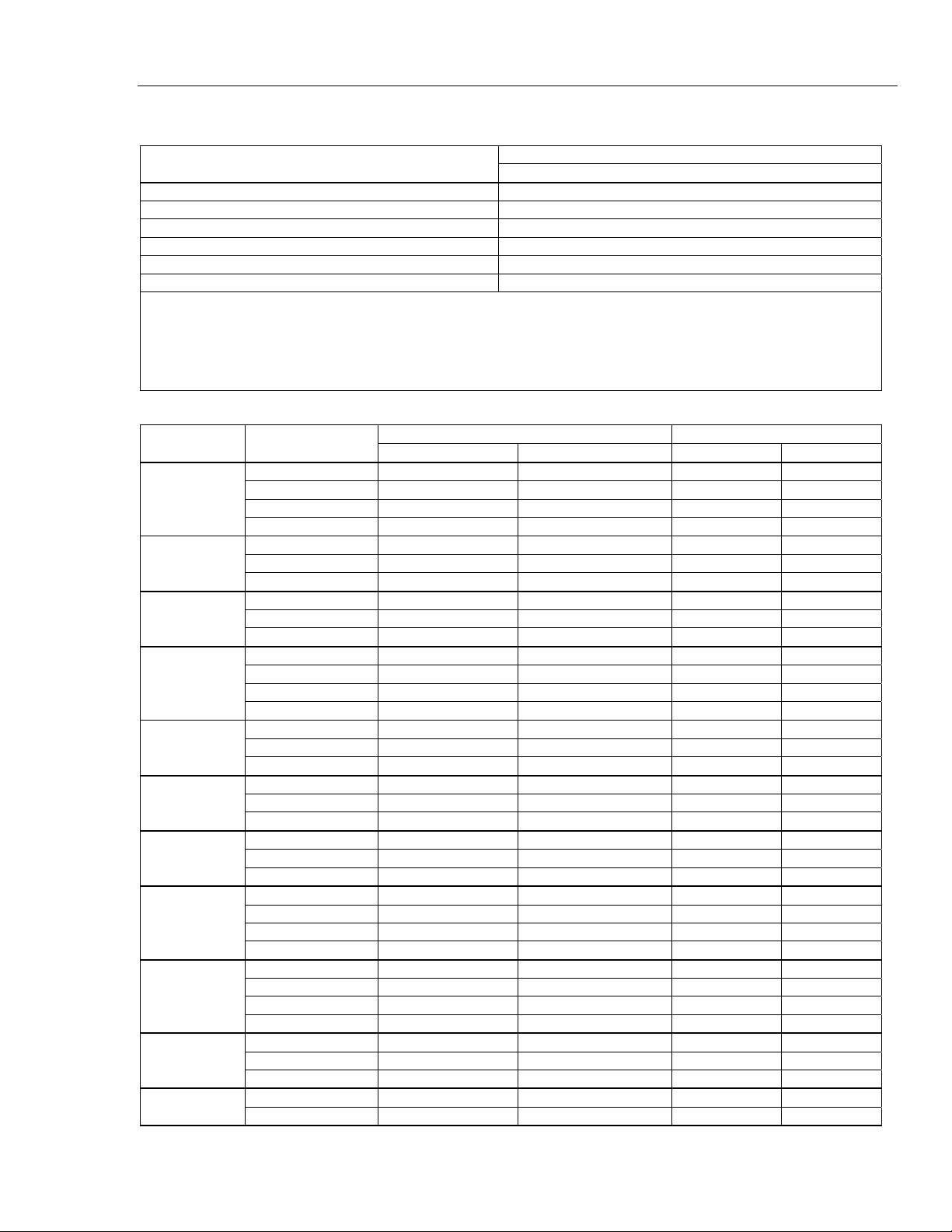
Frequency Sourcing
Range
Specification
2 Year
Sine Wave: 0.1 Hz to 10.99 Hz 0.01 Hz
Square Wave: 0.01 Hz to 10.99 Hz 0.01 Hz
Sine and Square Wave: 11.00 Hz to 109.99 Hz 0.1 Hz
Sine and Square Wave: 110.0 Hz to 1099.9 Hz 0.1 Hz
Sine and Square Wave: 1.100 kHz to 21.999 kHz 0.002 kHz
Sine and Square Wave: 22.000 kHz to 50.000 kHz 0.005 kHz
Waveform Choices: Zero-symmetric sine wave or positive 50 % duty-cycle square wave
Square Wave Amplitude: 0.1 to 15 V p-p
Square Wave Amplitude Accuracy, 0.01 to 1 kHz: 3 % p-p output + 75 mV, 1 kHz to 50 kHz: 10 % p-p output + 75 mV typical.
Sine Wave Amplitude: 0.1 to 30 V p-p
Sine Wave Amplitude Accuracy, 0.1 to 1 kHz: 3 % p-p output + 75 mV, 1 kHz to 50 kHz: 10 % p-p output + 75 mV typical.
Frequency specifications are valid when averaged ≥100 ms
Temperature, Thermocouples
Type
Range °C
Measure °C Source °C
1-Year 2 Year 1-Year 2 Year
E -250 to -200 1.3 2.0 0.6 0.9
-200 to -100 0.5 0.8 0.3 0.4
-100 to 600 0.3 0.4 0.3 0.4
600 to 1000 0.4 0.6 0.2 0.3
N -200 to -100 1.0 1.5 0.6 0.9
-100 to 900 0.5 0.8 0.5 0.8
900 to 1300 0.6 0.9 0.3 0.4
J -210 to -100 0.6 0.9 0.3 0.4
-100 to 800 0.3 0.4 0.2 0.3
800 to 1200 0.5 0.8 0.3 0.3
K -200 to -100 0.7 1.0 0.4 0.6
-100 to 400 0.3 0.4 0.3 0.4
400 to 1200 0.5 0.8 0.3 0.4
1200 to 1372 0.7 1.0 0.3 0.4
T -250 to -200 1.7 2.5 0.9 1.4
-200 to 0 0.6 0.9 0.4 0.6
0 to 400 0.3 0.4 0.3 0.4
B 600 to 800 1.3 2.0 1.0 1.5
800 to 1000 1.0 1.5 0.8 1.2
1000 to 1820 0.9 1.3 0.8 1.2
R -20 to 0 2.3 2.8 1.2 1.8
0 to 100 1.5 2.2 1.1 1.7
100 to 1767 1.0 1.5 0.9 1.4
S -20 to 0 2.3 2.8 1.2 1.8
0 to 200 1.5 2.1 1.1 1.7
200 to 1400 0.9 1.4 0.9 1.4
1400 to 1767 1.1 1.7 1.0 1.5
C
(W5Re/W26Re)
0 to 800 0.6 0.9 0.6 0.9
800 to 1200 0.8 1.2 0.7 1.0
1200 to 1800 1.1 1.6 0.9 1.4
1800 to 2316 2.0 3.0 1.3 2.0
L -200 to -100 0.6 0.9 0.3 0.4
-100 to 800 0.3 0.4 0.2 0.3
800 to 900 0.5 0.8 0.2 0.3
U -200 to 0 0.6 0.9 0.4 0.6
0 to 600 0.3 0.4 0.3 0.4
753/754
Calibration Manual
8
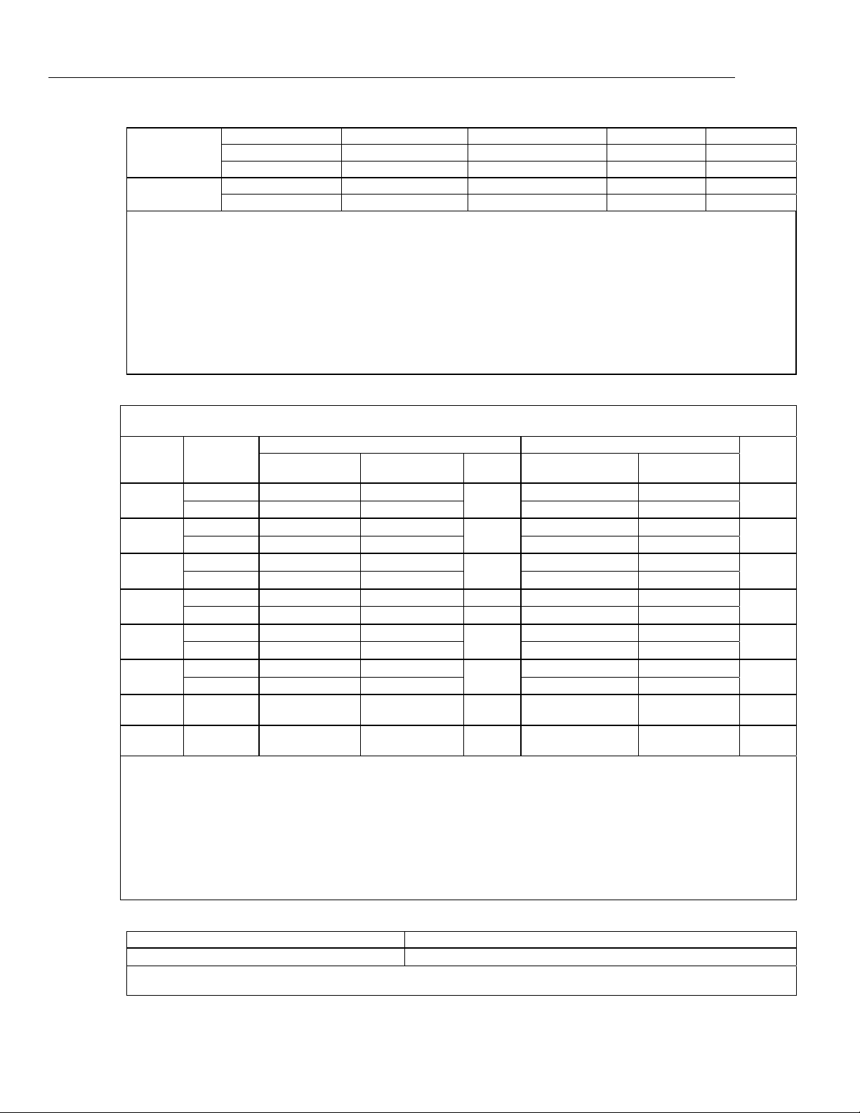
BP 0 to 1000 1.0 1.5 0.4 0.6
1000 to 2000 1.6 2.4 0.6 0.9
2000 to 2500 2.0 3.0 0.8 1.2
XK -200 to 300 0.2 0.3 0.2 0.5
300 to 800 0.4 0.6 0.3 0.6
Sensor inaccuracies not included.
Accuracy with external cold junction; for internal junction add 0.2 °C
Resolution: 0.1 °C
Temperature Scale: ITS-90 or IPTS-68, selectable (90 is default)
Compensation: ITS-90 per NIST Monograph 175 for B,R,S,E,J,K,N,T; IPTS-68 per IEC 584-1 for B,R,S,E,J,K,T; IPTS-68 per DIN 43710 for L,U.
GOST P 8.585-2001 (Russia) for BP and XK, ASTM E988-96 for C (W5Re/W26Re)
Temperature Coefficient: 0.05 °C/ °C (<18 °C or >28 °C)
0.07 °C/ °C for C type >1800 °C and for BP type >2000 °C
Instrument Operating Temperature: 0 to 50 °C for C and BP type thermocouples / -10 to 50 °C for all other types
Normal Mode Rejection: 40 dB at 50 Hz or 60 Hz nominal
For sourcing thermocouple voltages, accuracy is not specified in RF fields >1 V/m, 80 MHz to 700 MHz.
Temperature, Resistance Temperature Detectors
Temperature, RTDs
Degrees or % of Reading
[1]
Type (α) Range °C
Measure °C
[2]
Source °C
A
llowable
Excitation
Current
[3]
1-Year 2 Year
Source
Current
1-Year 2 Year
100 Ω
Pt(385)
-200 to 100
0.07 °C 0.14 °C
1 mA
0.05 °C 0.10 °C
0.1 to
10 mA
100 to 800
0.02 % + 0.05 °C 0.04 % + 0.10 °C 0.0125 % + 0.04 °C 0.025 % + 0.08 °C
200 Ω
Pt(385)
-200 to 100
0.07 °C 0.14 °C
500 μA
0.10 °C 0.20 °C
0.1 to
1 mA
100 to 630
0.02 % + 0.05 °C 0.04 % + 0.10 °C 0.017 % + 0.09 °C 0.034 % + 0.18 °C
500 Ω
Pt(385)
-200 to 100
0.07 °C 0.14 °C
250 μA
0.08 °C 0.16 °C
0.1 to
1 mA
100 to 630
0.02 % + 0.05 °C 0.04 % + 0.10 °C 0.017 % + 0.06 °C 0.034 % + 0.12 °C
1000 Ω
Pt(385)
-200 to 100
0.07 °C 0.14 °C 150 μA 0.06 °C 0.12 °C
0.1 to
1 mA
100 to 630
0.02 % + 0.05 °C 0.04 % + 0.10 °C
0.017 % + 0.05 °C 0.034 % + 0.10 °C
100 Ω
Pt(3916)
-200 to 100
0.07 °C 0.14 °C
1 mA
0.05 °C 0.10 °C
0.1 to
10 mA
100 to 630
0.02 % + 0.05 °C 0.04 % + 0.10 °C 0.0125 % + 0.04 °C 0.025 % + 0.08 °C
100 Ω
Pt(3926)
-200 to 100
0.08 °C 0.16 °C
1 mA
0.05 °C 0.10 °C
0.1 to
10 mA
100 to 630
0.02 % + 0.06 °C 0.04 % + 0.12 °C 0.0125 % + 0.04 °C 0.025 % + 0.08 °C
10 Ω
Cu(427)
-100 to 260
0.2 °C 0.4 °C
3 mA
0.2 °C 0.4 °C
1 to
10 mA
120 Ω
Ni(672)
-80 to 260
0.1 °C 0.2 °C
1 mA
0.04 °C 0.08 °C
0.1 to
10 mA
[1] Specifications are valid to k=3
Sensor inaccuracies not included
[2] For two and three-wire RTD measurements, add 0.4 °C to the specifications.
Resolution: 0.01 °C except 0.1 °C for 10 Ω Cu(427)
Temperature Coefficient: 0.01 °C/°C for measure, 0.02 °C/°C (<18 °C or >28 °C) for source
[3] Supports pulsed transmitters and PLCs with pulse times as short as 1 ms
RTD Reference:
Pt(385): IEC 60751, 2008
Pt(3916): JIS C 1604, 1981
Pt(3926), Cu(427), Ni(672): Minco Application Aid #18
Loop Power
Open Circuit Loaded Circuit
26 V ±10 %
18 V minimum at 22 mA
Short circuit protected to 25 mA
Output Resistance: 250 Ω nominal