754_____cmeng0000.pdf - 第39页
Documenting Process Calibrator HART Mode Verification (754 Only) 31 It is not necessary to open the case or adjust the Product to do this test. Make the necessary connections and verify that the Product responds as neces…
753/754
Calibration Manual
30
Loop Power
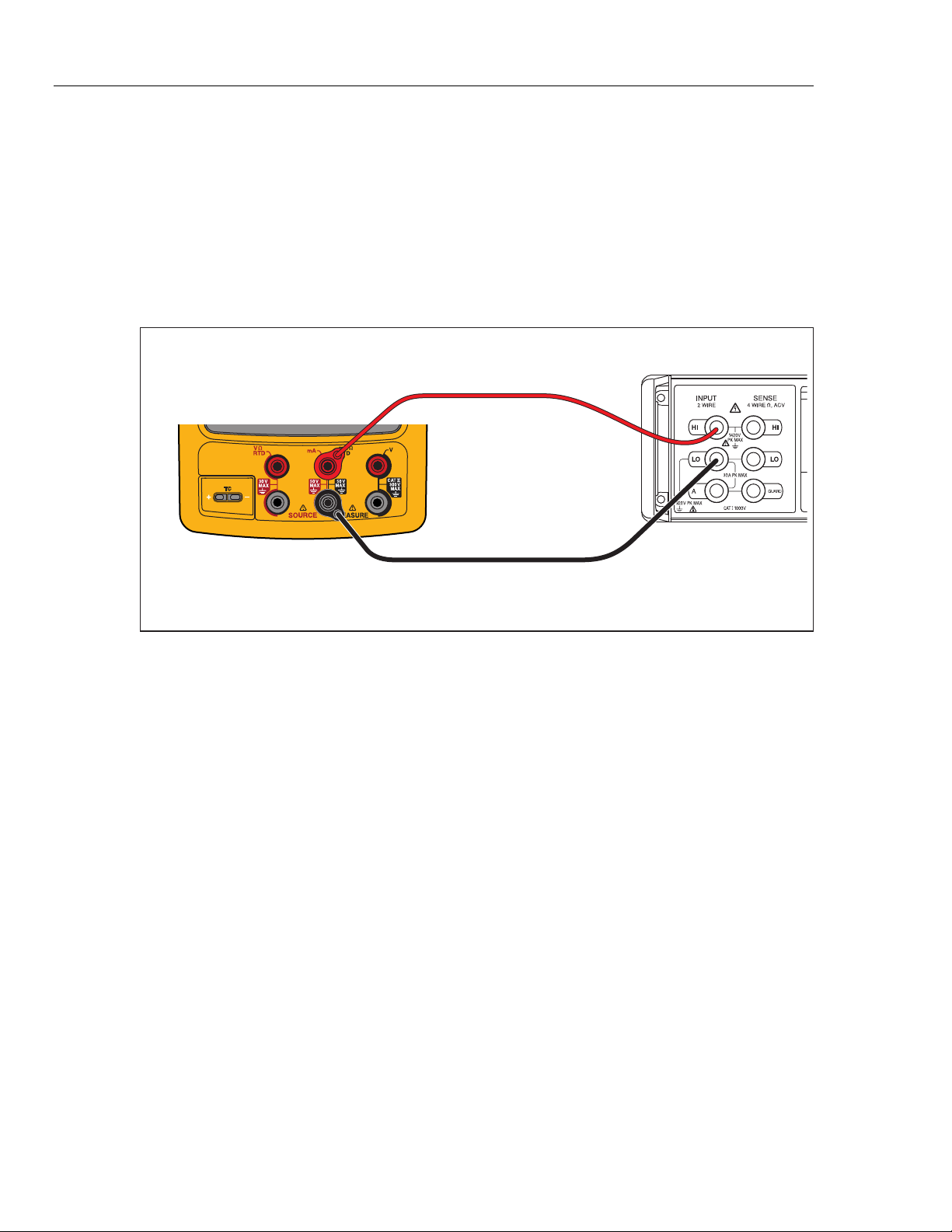
To verify the loop power function.
1. Connect the UUT to the 8508A DMM as shown in Figure 13.
2. On the UUT push s, , select Loop Power, and push again.
3. Observe the no-load voltage reading on the DMM and verify that it is within the
range 23.4 V to 28.6 V.
4. When complete, disable Loop Power through the setup menu or turn the UUT
off. This conserves battery life.
Fluke 75X
Fluke 8508A
gso15.eps
Figure 13. Loop Power Verification Connections
HART Mode Verification (754 Only)
The subsequent test makes sure that the 754 can communicate over a serial HART®
(Highway Addressable Remote Transducer) interface to a HART transmitter. The
calibrator communicates with virtually all HART transmitters and related software
versions. These are “supported transmitters”. All other transmitters are “generic”. A
Smart (HART) Pressure Transmitter is necessary for this procedure. The Rosemount
Models 1151 or 3051 are recommended (may be substituted with any HART
communicator protocol device).
This verification test is a pass or fail test. No calibration is necessary for the HART
mode. If the Product fails this test, repair is necessary. Refer to the 754 HART Mode
Users Guide for more data on the HART feature.
Documenting Process Calibrator
HART Mode Verification (754 Only)
31
It is not necessary to open the case or adjust the Product to do this test. Make the
necessary connections and verify that the Product responds as necessary.
1. Push s. The first setup screen shows.
2. Push or to select HART Channel.
3. Push .
4. Push or to select mA Jack.
5. Push .
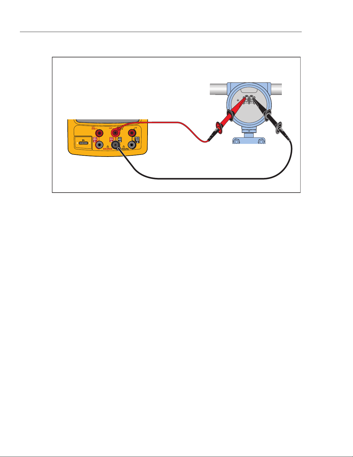
6. Connect the Product to the HART transmitter as shown in Figure 15.
7. Push r to start HART mode. If necessary, push the applicable softkey to enable
Loop Power.
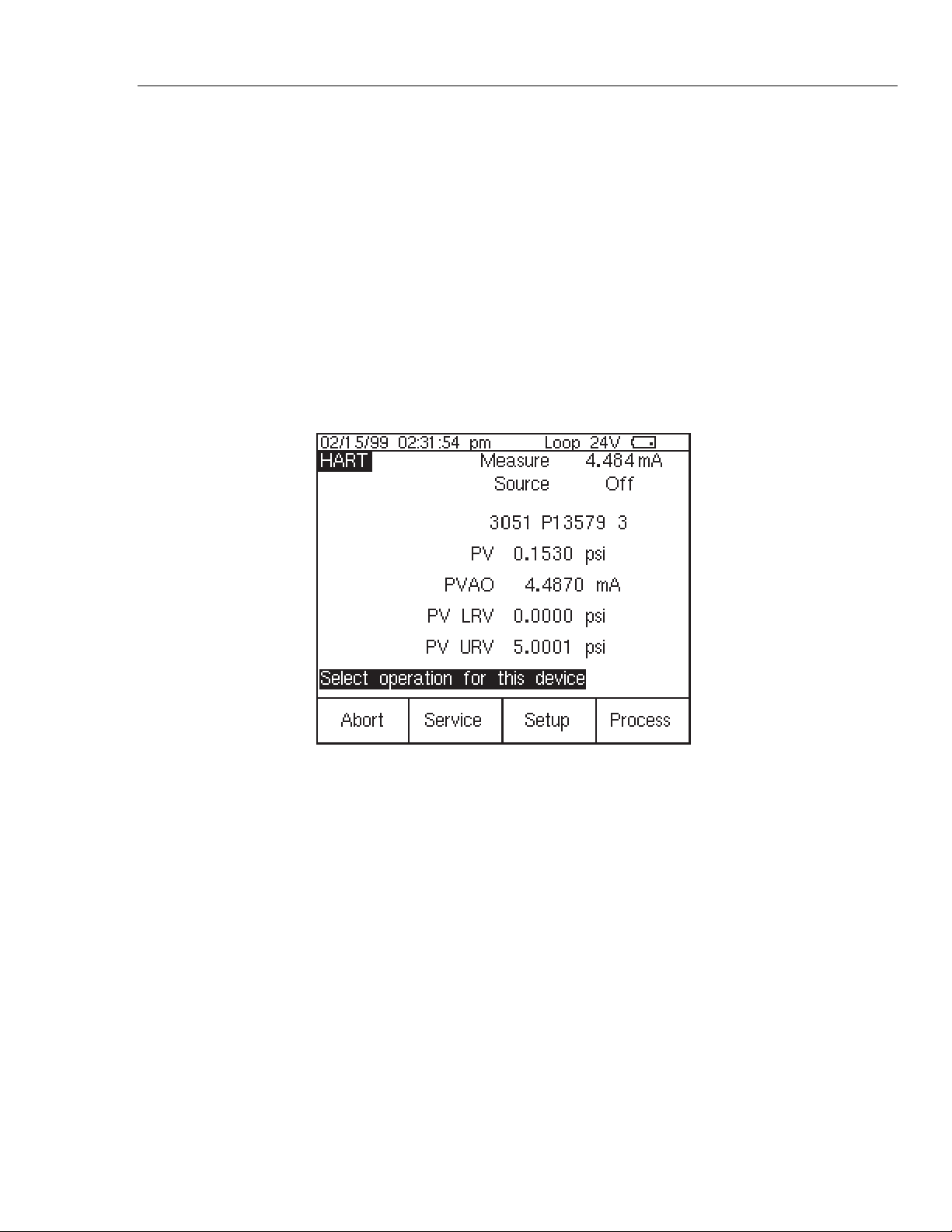
The Product recognizes and identifies the HART transmitter. When used with a
Model 3051, the Product shows:
qb20s.bmp
Figure 14. Active Device Screen
The Active Device screen gives this data for all HART transmitters, supported or
generic:
• Poll address (if not 0)
• Model number and Tag ID
• PV (Primary Variable)
• PVAO (digital representation of the Analog Output)
• PV LRV (PV Lower Range Value)
• PV URV (PV Upper Range Value)
• Softkeys for accessing HART operation menus
8. Communication to the HART transmitter has been established if step seven has
been completed. The Product has passed the HART mode verification test.
9. If the calibrator does not recognize the transmitter, the test has failed and Product
repair is necessary. Speak to your nearest approved Fluke Service Center for
servicing.
753/754
Calibration Manual
32
10. Disconnect all test equipment.
Fluke 75X
gks43.eps
Figure 15. HART Mode Verification Connections
Calibration
Calibration is necessary only if the UUT does not pass verification. Always re-verify
after calibration.
Calibration for the Product is done with internal software. There are no physical
adjustments (except for three potentiometers used for common-mode error, explained
later in this chapter). The subsequent instructions for calibration are minimal because of
the built-in guided procedures. The internal software routines give step-by-step prompts
for the correct stimulus or measurement. The guided procedures also illustrate which
terminals (jacks) to use when you apply a stimulus, reading a measurement, or which
terminals must be to be shorted with jumpers. Follow the instructions carefully to
complete each calibration routine.
Equipment Required for Calibration
The necessary accuracy of the source or measurement does not always correspond to the
number of decimal places indicated on the UUT’s display. For example, if you calibrate
Frequency Measure, when the display requests a source value of 5.00000 V at
1.00000 kHz, the necessary accuracies are not of that magnitude. Use the measurement
and source equipment suggested at the start of the Performance Verification Test.
Calibration Status Indicator
The calibration display is accessed by when you push s and then the Prev. Page
softkey. At the top of the display is the Calibration Status followed by a number. This
number moves forward after each subroutine is completed and the new constants are
kept. When you do a complete calibration, the Product moves the Calibration Status by 4.
Because the Calibration Status number is changed only by a re-calibration, it can be used
to make sure that previous calibration constants have not been changed.
How to Enter Calibration
In the calibration setup screen, push W to calibrate. The calibration screen requests
a password, 1234 is the default. After you put in the password, push Z to continue.
The password is user-settable.