754_____cmeng0000.pdf - 第33页
Documenting Process Calibrator Performance Verification Tests 25 Table 13. Temperature Meas ure Verification Input dcmV (referenced to 0 °C) Minimum 1-Year °C Maximum 1-Year °C Minimum 2-Year °C Maximum 2-Year °C -5.550 …
753/754
Calibration Manual
24
5522A
CALIBRATOR
Fluke 75X
Room Temperature
Lab Bath
Fluke 1551A Ex
Thermometer
Fluke 5522A
TYPE-K
Thermocouple
Wire
CuCu
gso12.eps
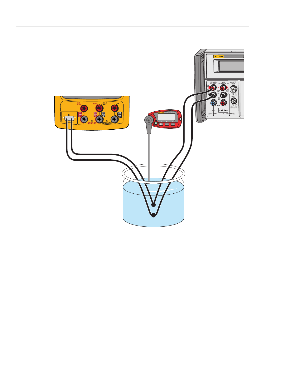
Figure 10. Temperature Measure (TC) Verification Connections
Documenting Process Calibrator
Performance Verification Tests
25
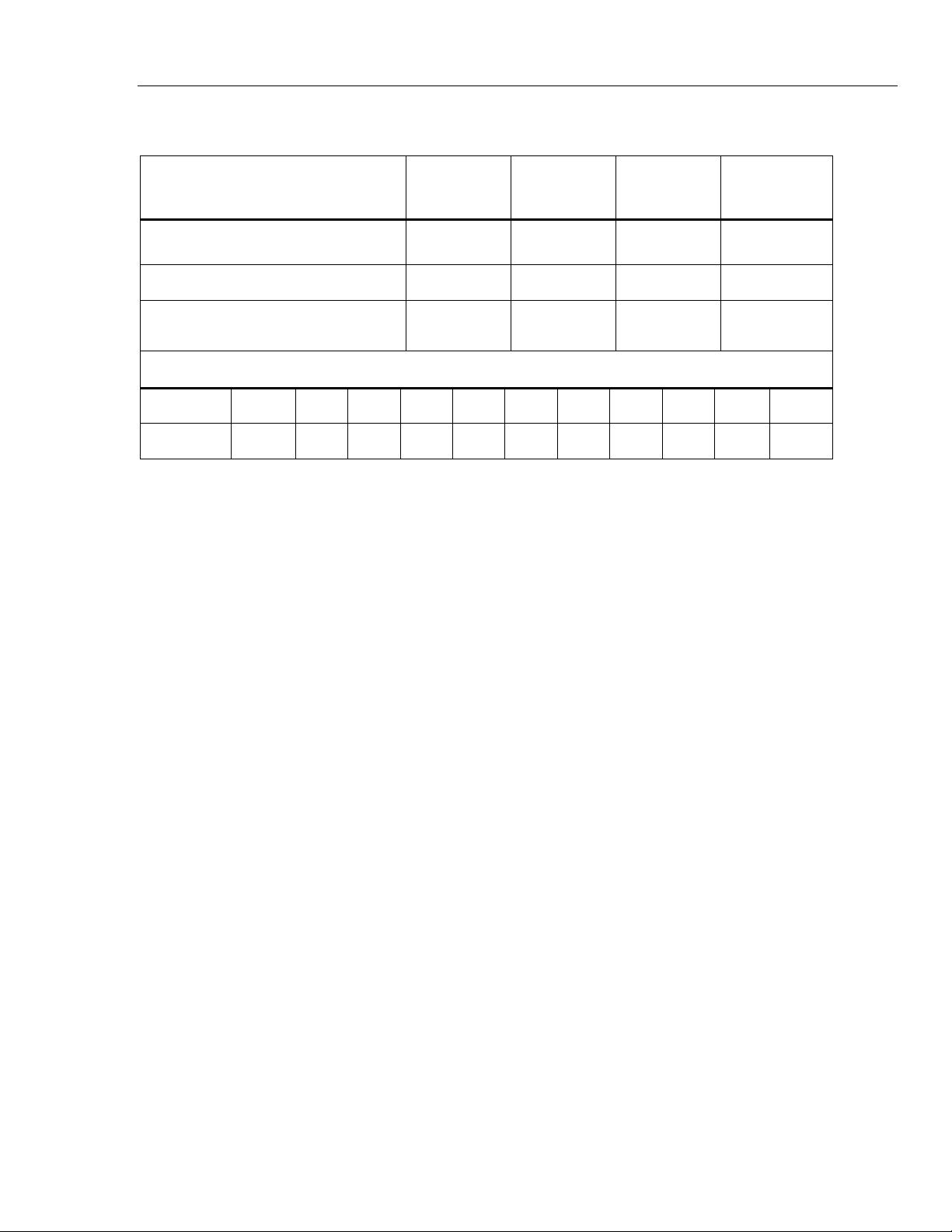
Table 13. Temperature Measure Verification
Input dcmV (referenced to 0 °C)
Minimum
1-Year °C
Maximum
1-Year °C
Minimum
2-Year °C
Maximum
2-Year °C
-5.550 mV (-180 °C) -180.9 -179.1 -181.2 -178.8
0.000 mV (0 °C) -0.5 0.5 -0.6 0.6
52.410 mV (1300 °C) 1299.1 1300.9 1298.8 1301.2
Lag Bath Reference Table, Type K, ITS-90
Tem
p
. °C 18 19 20 21 22 23 24 25 26 27 28
mV 0.718 0.758 0.798 0.838 0.879 0.919 0.960 1.000 1.041 1.081 1.122
Thermocouple Source
To verify the thermocouple source function:
Note
This test uses a Type-K thermocouple setting on the UUT.
1. Use Type-K thermocouple wire and copper wire to connect the 8508A to the
UUT -TC jack as shown in Figure 10 (the 8508A is used in place of the 5522A).
The type K-to-copper junctions must be welded or made with tight screw
terminals and submersed in the lag bath (room temperature). Use the standard
thermometer (0.1 % accuracy) to measure the temperature of the lag bath.
2. Set the UUT to the thermocouple source function, linear mode, TC type K, ITS-
90 scale, internal reference, and °C.
3. Set the 8508A to measure mV dc.
4. Stop for a minimum of 1 minute for thermal “emfs” (caused by insertion of the
connectors) to dissipate, and let the lag bath become stable for a minimum of 15
minutes.
5. Source each of the temperatures in Table 14 from the UUT. At each point,
correct the DMM measured voltage. To do this, add the millivolt equivalent of
the Type-K junction at the lag bath temperature (use the Type-K ITS-90 chart).
6. Continue through the test points. See if the value shown on the UUT is in the
range shown in the applicable column in Table 14.
7. When you complete the test, push on the UUT two times to turn the source
function off. This conserves battery life.
753/754
Calibration Manual
26
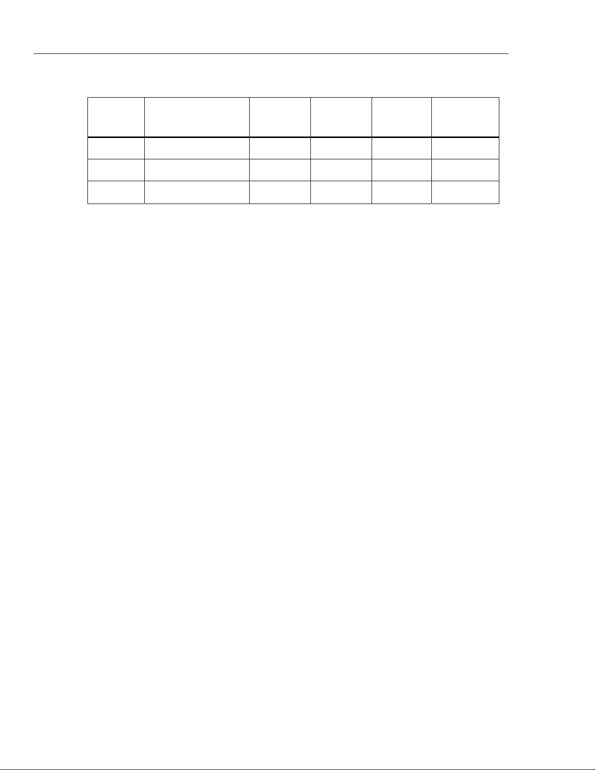
Table 14. Temperature Source Verification (Type-K Thermocouple, ITS-90)
UUT
Output
Nominal DC mV
Minimum
1-Year
Maximum
1-Year
Minimum
2-Year
Maximum
2-Year
-180 °C -5.5504 -5.5616 -5.539 -5.5653 -5.5353
0 °C 0.0000 -0.0197 0.0197 -0.0237 0.0237
1300 °C 52.4103 52.3928 52.4277 52.3893 52.4312
RTD Measure, Four-Wire
Note
It is necessary to use a separate verification procedure for the three-wire
RTD measure function because it uses different circuits. The two-wire RTD
measure circuit is tested during the Ohms Measure procedure. If a 5522A is
not available, replace it with a variable resistance source such as a general
resistance RTD-100 RTD simulator and a DMM to measure the variable
resistance source for accuracy. Use the resistance equivalents shown in
Table 15.
To verify the four-wire RTD Measure function:
1. Connect the UUT to the 5522A as shown in Figure 11. Use a four-wire
connection and four-wire compensation.
2. Set the UUT to the RTD measure function, Pt100 (385), ITS-90 scale, and four-
wire termination.
3. Set the 5522A to RTD, Pt100 (385) at -180 °C, ITS-90 scale, and comp four-
wire.
4. Set the 5522A to [Operate].
5. See if the value shown on the UUT is in the range shown in the applicable
column in Table 15.
6. Continue through the test points.
7. When you complete the test, set the 5522A to STANDBY.