754_____cmeng0000.pdf - 第40页
753/754 Calibration Manual 32 10. Disconnect all test equipment. Fluke 75X gks43.eps Figure 15. HART Mode Ve rification Connect ions Calibration Calibration is necessary only if the UUT do es not pass verification. Alway…
Documenting Process Calibrator
HART Mode Verification (754 Only)
31
It is not necessary to open the case or adjust the Product to do this test. Make the
necessary connections and verify that the Product responds as necessary.
1. Push s. The first setup screen shows.
2. Push or to select HART Channel.
3. Push .
4. Push or to select mA Jack.
5. Push .
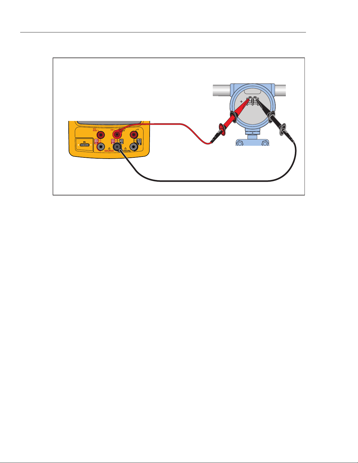
6. Connect the Product to the HART transmitter as shown in Figure 15.
7. Push r to start HART mode. If necessary, push the applicable softkey to enable
Loop Power.
The Product recognizes and identifies the HART transmitter. When used with a
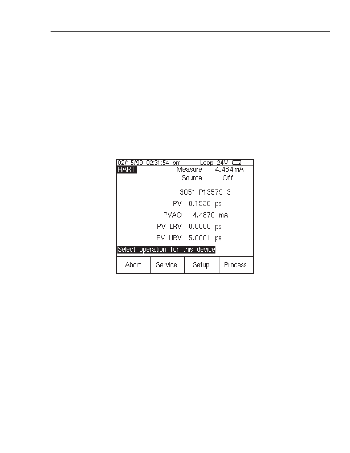
Model 3051, the Product shows:
qb20s.bmp
Figure 14. Active Device Screen
The Active Device screen gives this data for all HART transmitters, supported or
generic:
• Poll address (if not 0)
• Model number and Tag ID
• PV (Primary Variable)
• PVAO (digital representation of the Analog Output)
• PV LRV (PV Lower Range Value)
• PV URV (PV Upper Range Value)
• Softkeys for accessing HART operation menus
8. Communication to the HART transmitter has been established if step seven has
been completed. The Product has passed the HART mode verification test.
9. If the calibrator does not recognize the transmitter, the test has failed and Product
repair is necessary. Speak to your nearest approved Fluke Service Center for
servicing.
753/754
Calibration Manual
32
10. Disconnect all test equipment.
Fluke 75X
gks43.eps
Figure 15. HART Mode Verification Connections
Calibration
Calibration is necessary only if the UUT does not pass verification. Always re-verify
after calibration.
Calibration for the Product is done with internal software. There are no physical
adjustments (except for three potentiometers used for common-mode error, explained
later in this chapter). The subsequent instructions for calibration are minimal because of
the built-in guided procedures. The internal software routines give step-by-step prompts
for the correct stimulus or measurement. The guided procedures also illustrate which
terminals (jacks) to use when you apply a stimulus, reading a measurement, or which
terminals must be to be shorted with jumpers. Follow the instructions carefully to
complete each calibration routine.
Equipment Required for Calibration
The necessary accuracy of the source or measurement does not always correspond to the
number of decimal places indicated on the UUT’s display. For example, if you calibrate
Frequency Measure, when the display requests a source value of 5.00000 V at
1.00000 kHz, the necessary accuracies are not of that magnitude. Use the measurement
and source equipment suggested at the start of the Performance Verification Test.
Calibration Status Indicator
The calibration display is accessed by when you push s and then the Prev. Page
softkey. At the top of the display is the Calibration Status followed by a number. This
number moves forward after each subroutine is completed and the new constants are
kept. When you do a complete calibration, the Product moves the Calibration Status by 4.
Because the Calibration Status number is changed only by a re-calibration, it can be used
to make sure that previous calibration constants have not been changed.
How to Enter Calibration
In the calibration setup screen, push W to calibrate. The calibration screen requests
a password, 1234 is the default. After you put in the password, push Z to continue.
The password is user-settable.

Documenting Process Calibrator
Calibration
33
On the calibration screen, the step that has bolded text is the selected step.
Set Calibration Date sets the date that the Product shows for calibration at start-up. In
most instances this is the date that the Product last passed the Performance Verification.
There are four adjustment procedures:
• Adjust Source
• Adjust Loop
• Adjust Measure
• Adjust Thermocouple
Each of these items shows the last time this step was competed.
• When you push the Exit softkey, the Product goes out of Calibration mode and
starts.
• When you push the Change Calibration Password softkey the screen
changes to the password screen.
• When you push the Continue softkey, the Product continues with the selected
step.
Calibration Constant Out of Bounds
If one or more of the calibration stimuli (or measurements) is out of range during a
calibration routine, or the cabling is incorrect, the message [Error - Calibration Constant
Out of Bounds] shows at the end of the routine. A general fault with the UUT can also be
indicated by this error. The fault has to be corrected before you do the full sub-routine.
How to Calibrate
Follow these general instructions for all calibrations:
• Operate the UUT on battery power. Make sure the battery is fully charged.
• Let each piece of calibration equipment meet its specified warm up period.
• Let the UUT warm up a minimum of 10 minutes.
• Source is only powered when it is used. A separate warm up for 10 minutes is
necessary when you adjust source vdc, source ohms, source TC, source RTD, or
source Hz. When you do a full adjust, a 10-minute warm up pause at the start of
the volts dc source warms up the Product for all source steps.
• For each calibration, make sure the calibration equipment is stable and that the
“unsettled” annunciator on the UUT is not shown.
Continue:
1. Turn on the UUT.
2. Push s and then the Prev. Page softkey.
3. Push the Calibrate softkey to open the password screen
4. Input the password (the default password is 1234) and then push the Continue
softkey.
5. Use and D to move the black text to the step to run. Push the Continue
softkey to start a procedure
Each adjustment procedure will give connection instructions and signal levels
needed for the step.
6. When the display prompts you for an input of 100.000 mV dc but shows an range