754_____cmeng0000.pdf - 第17页
Documenting Process Calibrator Performance Verification Tests 9 Performance Verification Tests Fluke recommends re-certification each year. To re-certify, do the verification procedure. If test points are out of toleranc…
753/754
Calibration Manual
8
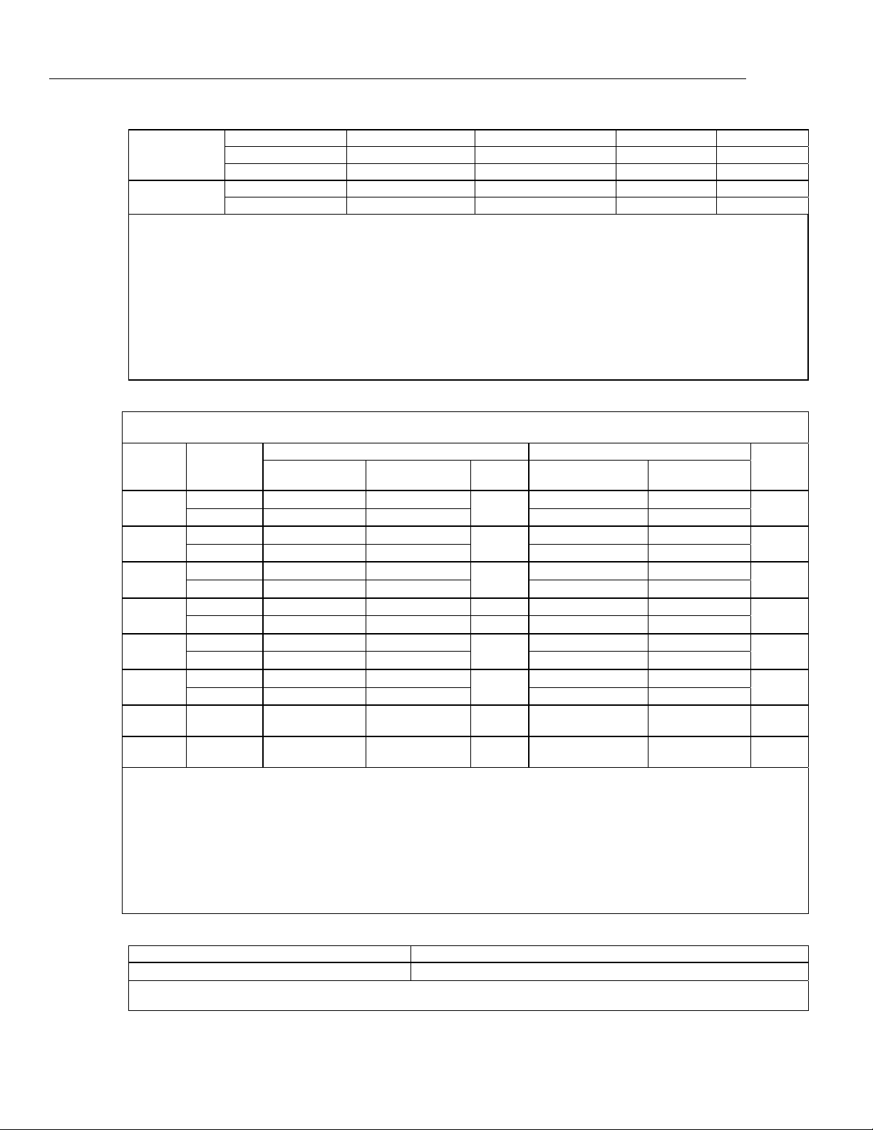
BP 0 to 1000 1.0 1.5 0.4 0.6
1000 to 2000 1.6 2.4 0.6 0.9
2000 to 2500 2.0 3.0 0.8 1.2
XK -200 to 300 0.2 0.3 0.2 0.5
300 to 800 0.4 0.6 0.3 0.6
Sensor inaccuracies not included.
Accuracy with external cold junction; for internal junction add 0.2 °C
Resolution: 0.1 °C
Temperature Scale: ITS-90 or IPTS-68, selectable (90 is default)
Compensation: ITS-90 per NIST Monograph 175 for B,R,S,E,J,K,N,T; IPTS-68 per IEC 584-1 for B,R,S,E,J,K,T; IPTS-68 per DIN 43710 for L,U.
GOST P 8.585-2001 (Russia) for BP and XK, ASTM E988-96 for C (W5Re/W26Re)
Temperature Coefficient: 0.05 °C/ °C (<18 °C or >28 °C)
0.07 °C/ °C for C type >1800 °C and for BP type >2000 °C
Instrument Operating Temperature: 0 to 50 °C for C and BP type thermocouples / -10 to 50 °C for all other types
Normal Mode Rejection: 40 dB at 50 Hz or 60 Hz nominal
For sourcing thermocouple voltages, accuracy is not specified in RF fields >1 V/m, 80 MHz to 700 MHz.
Temperature, Resistance Temperature Detectors
Temperature, RTDs
Degrees or % of Reading
[1]
Type (α) Range °C
Measure °C
[2]
Source °C
A
llowable
Excitation
Current
[3]
1-Year 2 Year
Source
Current
1-Year 2 Year
100 Ω
Pt(385)
-200 to 100
0.07 °C 0.14 °C
1 mA
0.05 °C 0.10 °C
0.1 to
10 mA
100 to 800
0.02 % + 0.05 °C 0.04 % + 0.10 °C 0.0125 % + 0.04 °C 0.025 % + 0.08 °C
200 Ω
Pt(385)
-200 to 100
0.07 °C 0.14 °C
500 μA
0.10 °C 0.20 °C
0.1 to
1 mA
100 to 630
0.02 % + 0.05 °C 0.04 % + 0.10 °C 0.017 % + 0.09 °C 0.034 % + 0.18 °C
500 Ω
Pt(385)
-200 to 100
0.07 °C 0.14 °C
250 μA
0.08 °C 0.16 °C
0.1 to
1 mA
100 to 630
0.02 % + 0.05 °C 0.04 % + 0.10 °C 0.017 % + 0.06 °C 0.034 % + 0.12 °C
1000 Ω
Pt(385)
-200 to 100
0.07 °C 0.14 °C 150 μA 0.06 °C 0.12 °C
0.1 to
1 mA
100 to 630
0.02 % + 0.05 °C 0.04 % + 0.10 °C
0.017 % + 0.05 °C 0.034 % + 0.10 °C
100 Ω
Pt(3916)
-200 to 100
0.07 °C 0.14 °C
1 mA
0.05 °C 0.10 °C
0.1 to
10 mA
100 to 630
0.02 % + 0.05 °C 0.04 % + 0.10 °C 0.0125 % + 0.04 °C 0.025 % + 0.08 °C
100 Ω
Pt(3926)
-200 to 100
0.08 °C 0.16 °C
1 mA
0.05 °C 0.10 °C
0.1 to
10 mA
100 to 630
0.02 % + 0.06 °C 0.04 % + 0.12 °C 0.0125 % + 0.04 °C 0.025 % + 0.08 °C
10 Ω
Cu(427)
-100 to 260
0.2 °C 0.4 °C
3 mA
0.2 °C 0.4 °C
1 to
10 mA
120 Ω
Ni(672)
-80 to 260
0.1 °C 0.2 °C
1 mA
0.04 °C 0.08 °C
0.1 to
10 mA
[1] Specifications are valid to k=3
Sensor inaccuracies not included
[2] For two and three-wire RTD measurements, add 0.4 °C to the specifications.
Resolution: 0.01 °C except 0.1 °C for 10 Ω Cu(427)
Temperature Coefficient: 0.01 °C/°C for measure, 0.02 °C/°C (<18 °C or >28 °C) for source
[3] Supports pulsed transmitters and PLCs with pulse times as short as 1 ms
RTD Reference:
Pt(385): IEC 60751, 2008
Pt(3916): JIS C 1604, 1981
Pt(3926), Cu(427), Ni(672): Minco Application Aid #18
Loop Power
Open Circuit Loaded Circuit
26 V ±10 %
18 V minimum at 22 mA
Short circuit protected to 25 mA
Output Resistance: 250 Ω nominal
Documenting Process Calibrator
Performance Verification Tests
9
Performance Verification Tests
Fluke recommends re-certification each year. To re-certify, do the verification procedure.
If test points are out of tolerance, calibrate the Product and then re-verify. Two-year
specifications are included if the highest accuracy is not necessary.
Use the subsequent tests to make sure that the Product is inside its specification limits.
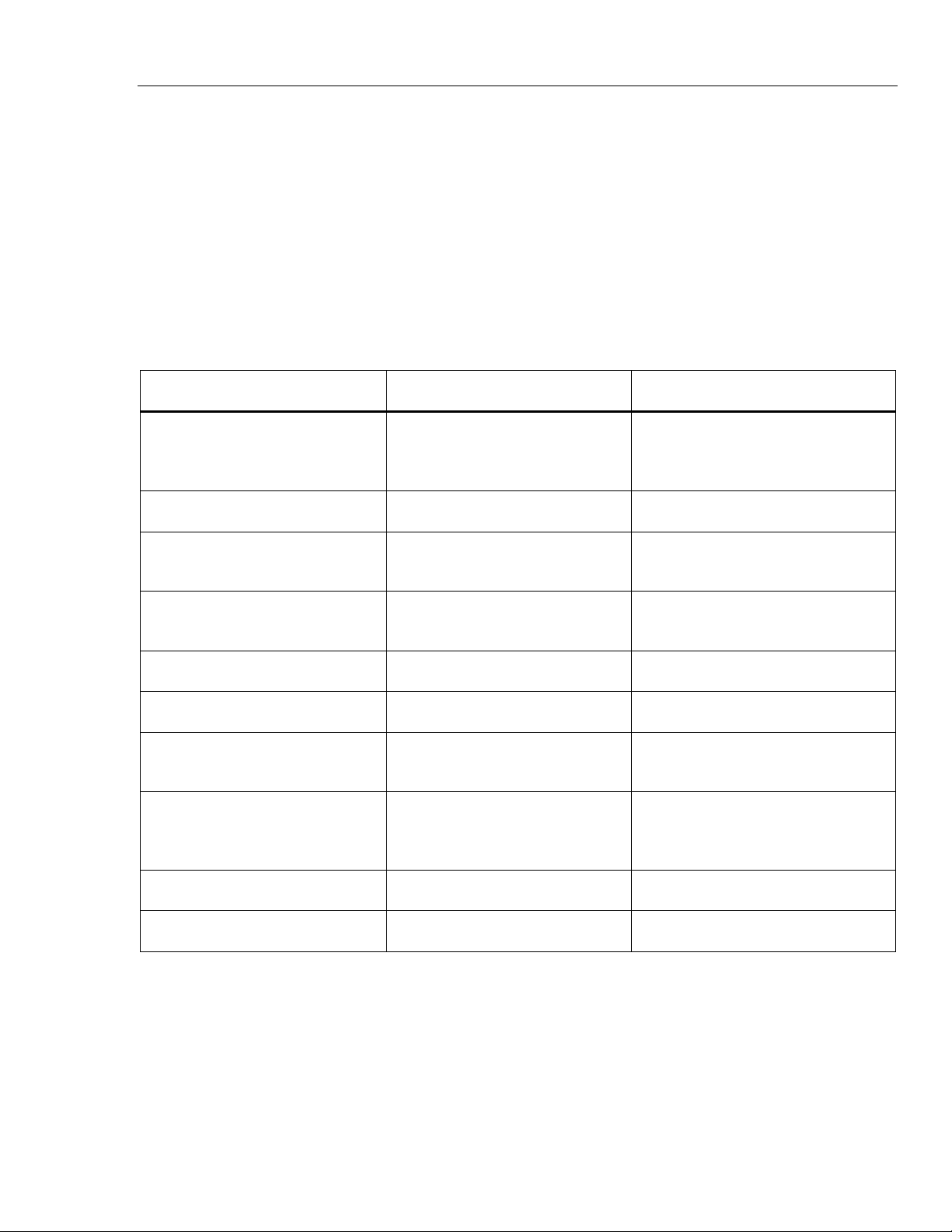
Verification Equipment
The equipment necessary for verification of the Product is shown in Table 2. If these
instruments are not available, you can replace them with other source and measure
instruments that have the same the minimum specification requirements.
Table 2. Equipment Required for Verification
Equipment Minimum Specification Recommended Model
Calibrator
0.002 % for DC Voltage,
Resistance and Current. 0.01 % for
AC Volt
Fluke 5522A
Frequency Counter 1 Hz to 50 kHz, 25 ppm timebase Tektronix FCA3000
Oscilloscope
1 Hz to 50 kHz (duty cycle accuracy
1 %)
Fluke 123
DMM
0.002 % for DC Voltage,
Resistance and Current
Fluke 8508A
2-Short jumpers banana type Fluke PN 944632
2-Test leads banana to banana type Fluke TL20
Thermocouple miniplug
polarize, with type-K thermocouple
welded to copper wire
see Figure 10
Lag bath
characterized by a 0.1 °C standard
thermometer (0.02 °C resolution)
and a 1-pint thermos bottle
Fluke 1551A Stik Thermometer, Dewar
Flask and Cap
Smart (HART) Pressure Transmitter HART communication protocol Rosemount 1151 or 3051
HART Interface Cable Assembly Fluke PN 3562160

753/754
Calibration Manual
10
How to Verify
For each procedure there is a table of test points and permitted readings. If the result of
the test is not in the range shown, the Unit Under Test (UUT) is out of tolerance and must
be re-calibrated or repaired if necessary. There are columns for 1 and 2-year
specifications wherever the specifications are different.
Follow these general instructions for all the tests:
• For all tests, operate the UUT on battery power. Make sure the battery is fully
charged.
• For measurement functions, push the Range softkey to lock the range on the
range specified in the test points table. It can be necessary to push the Range
softkey more than once.
• Ranges in the specification tables include the 10 % over-range capability. Range
names on the Product display do not include the 10 % over-range. For example,
the UUT display shows Range 100 mV, but the range is specified to 110 mV.
• Let each piece of verification equipment have its specified warm-up time.
• A minimum of 5 minutes is necessary for warm up. The source circuits shut off
when not in operation. A separate warm up is necessary when Source mode is
first used.
• For each test, make sure the verification equipment is stable and that the
“unsettled” annunciator on the UUT is not shown.
DC Volts Measurement
To verify the dc volts measurement function:
1. Connect the UUT to the 5522A as shown in Figure 1.
WCaution
To prevent possible damage to the Product, do not force a dual
banana plug between any two jacks in the horizontal
orientation. Doing so will damage the jacks. Use the supplied
jumper wire when needed for RTD measurements. A dual
banana plug may be used in the vertical orientation.
2. Set the UUT to the dc volts measurement function.
3. Push the Range softkey on the UUT to lock on the 100 mV range.
4. Set the 5522A to the first test point in Table 3.
5. See if the value shown on the UUT is in the range shown in the applicable
column.
6. Continue through the test points. Make sure to lock the UUT on the specified
range.
7. When you complete the test, set the 5522A to STANDBY.