754_____cmeng0000.pdf - 第38页
753/754 Calibration Manual 30 Loop Power To verify the loop power function. 1. Connect the UUT to the 8508A DMM as shown in Figure 13. 2. On the UUT push s , , select Loop Power, and push again. 3. Observe the no-loa…
Documenting Process Calibrator
Performance Verification Tests
29
RTD Source
To verify the RTD Source function:
1. Connect the UUT to the 8508A DMM as shown in Figure 8. Use a four-wire
connection transitioning to two-wires at the UUT.
2. Set the 8508A to 4-Wire Ohms, auto-range.
3. Set the UUT to the RTD source function, Pt100 (385) at -180 °C, ITS-90 scale.
4. See if the value shown on the DMM is in the range shown in the applicable
column in Table 17.
5. Continue through the test points.
6. When you complete the test, push on the UUT two times to turn the source
function off. This conserves battery life.
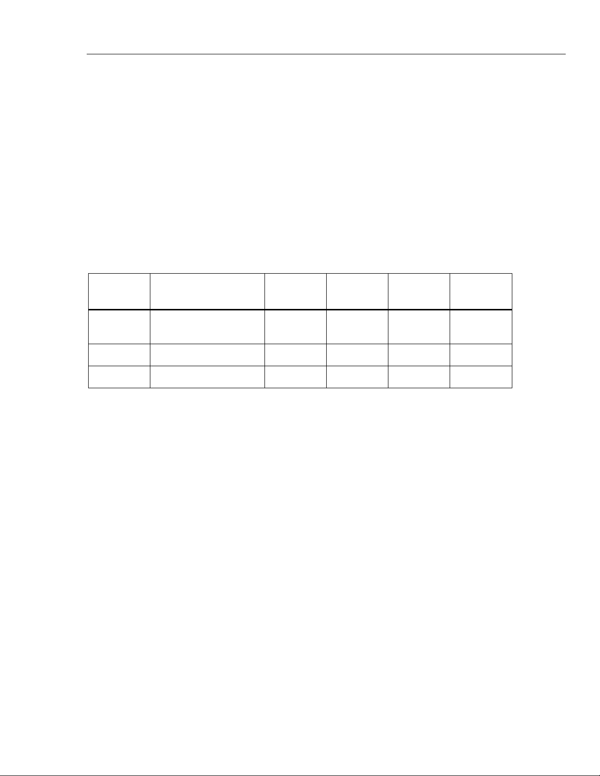
Table 17. RTD Source Verification (100W Pt (385))
UUT
Output
Nominal (Ohms)
Minimum
1-Year
Maximum
1-Year
Minimum
2-Year
Maximum
2-Year
-180 °C 27.096 27.075 27.118 27.054 27.139
100 °C 138.505 138.487 138.524 138.468 138.543
780 °C 369.712 369.6707 369.7532 369.630 369.795
753/754
Calibration Manual
30
Loop Power
To verify the loop power function.
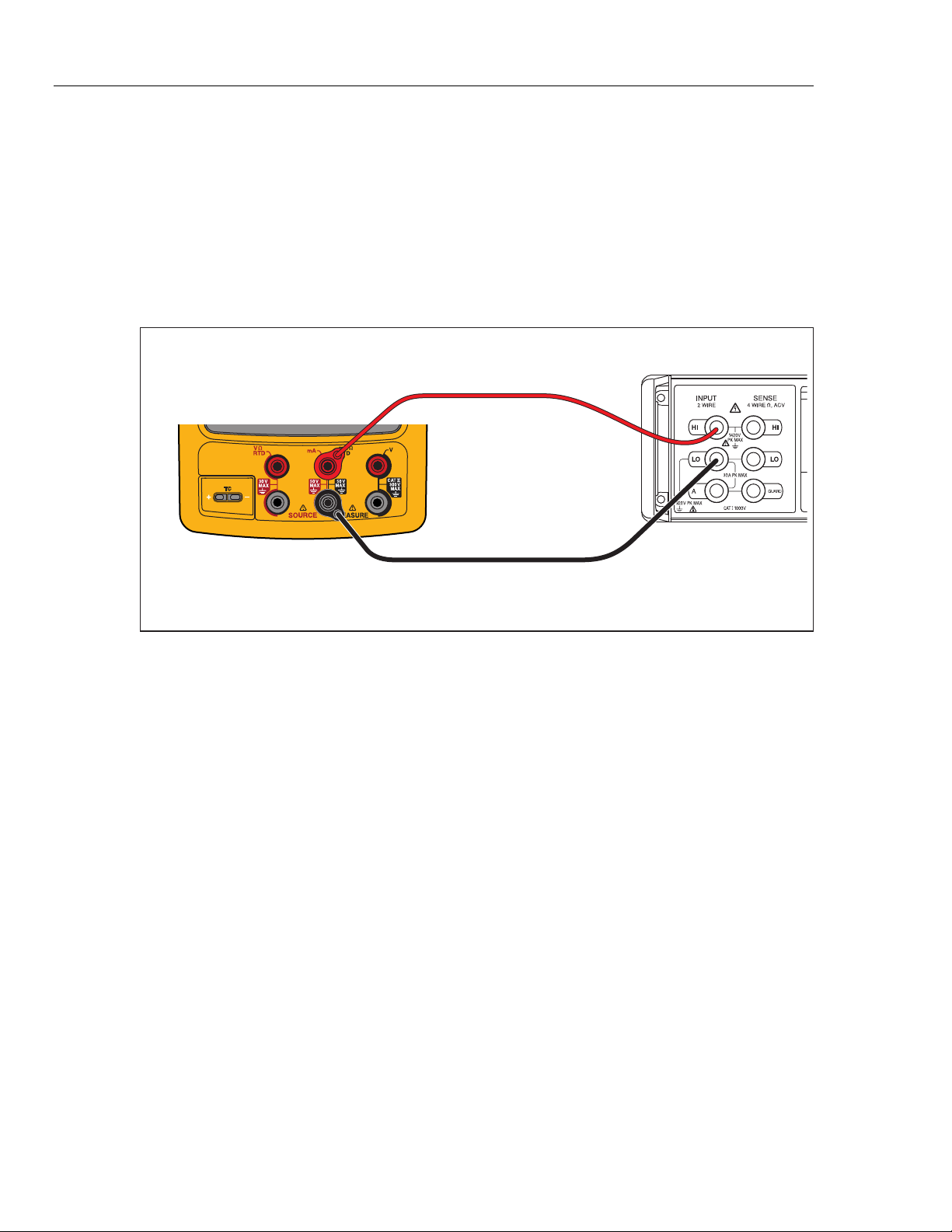
1. Connect the UUT to the 8508A DMM as shown in Figure 13.
2. On the UUT push s, , select Loop Power, and push again.
3. Observe the no-load voltage reading on the DMM and verify that it is within the
range 23.4 V to 28.6 V.
4. When complete, disable Loop Power through the setup menu or turn the UUT
off. This conserves battery life.
Fluke 75X
Fluke 8508A
gso15.eps
Figure 13. Loop Power Verification Connections
HART Mode Verification (754 Only)
The subsequent test makes sure that the 754 can communicate over a serial HART®
(Highway Addressable Remote Transducer) interface to a HART transmitter. The
calibrator communicates with virtually all HART transmitters and related software
versions. These are “supported transmitters”. All other transmitters are “generic”. A
Smart (HART) Pressure Transmitter is necessary for this procedure. The Rosemount
Models 1151 or 3051 are recommended (may be substituted with any HART
communicator protocol device).
This verification test is a pass or fail test. No calibration is necessary for the HART
mode. If the Product fails this test, repair is necessary. Refer to the 754 HART Mode
Users Guide for more data on the HART feature.
Documenting Process Calibrator
HART Mode Verification (754 Only)
31
It is not necessary to open the case or adjust the Product to do this test. Make the
necessary connections and verify that the Product responds as necessary.
1. Push s. The first setup screen shows.
2. Push or to select HART Channel.
3. Push .
4. Push or to select mA Jack.
5. Push .
6. Connect the Product to the HART transmitter as shown in Figure 15.
7. Push r to start HART mode. If necessary, push the applicable softkey to enable
Loop Power.
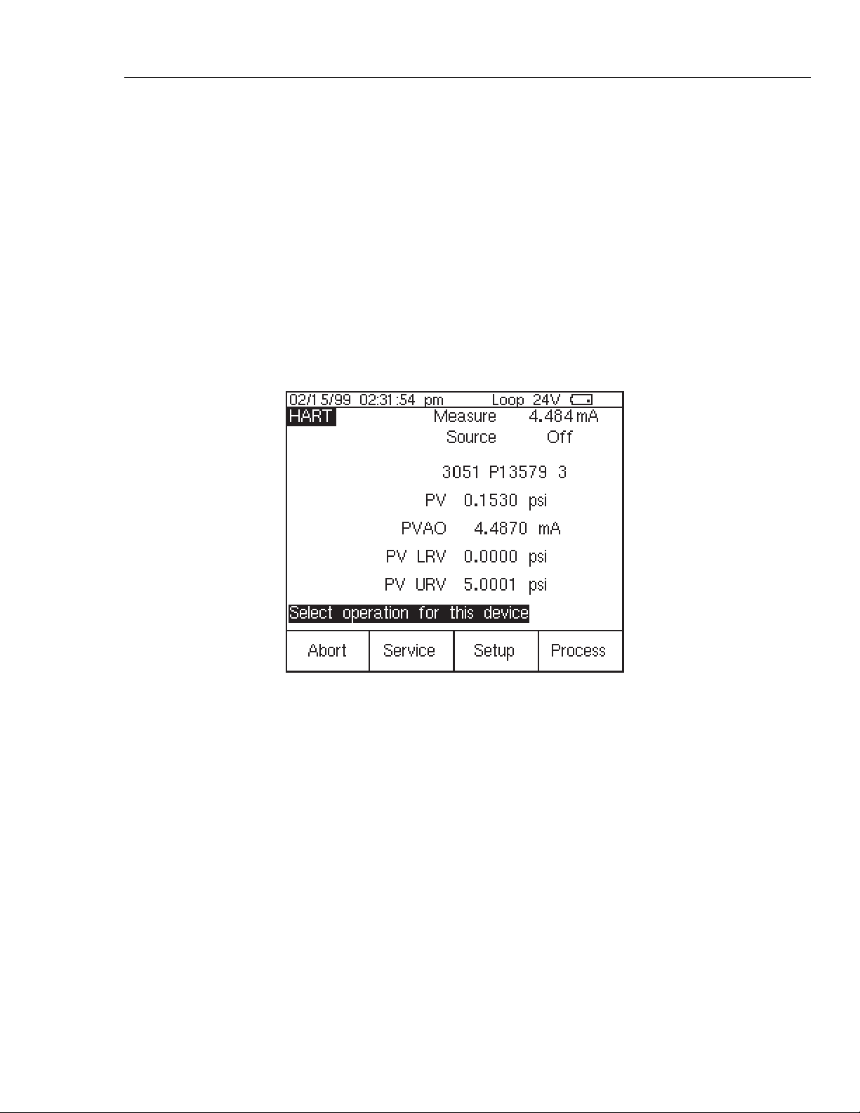
The Product recognizes and identifies the HART transmitter. When used with a
Model 3051, the Product shows:
qb20s.bmp
Figure 14. Active Device Screen
The Active Device screen gives this data for all HART transmitters, supported or
generic:
• Poll address (if not 0)
• Model number and Tag ID
• PV (Primary Variable)
• PVAO (digital representation of the Analog Output)
• PV LRV (PV Lower Range Value)
• PV URV (PV Upper Range Value)
• Softkeys for accessing HART operation menus
8. Communication to the HART transmitter has been established if step seven has
been completed. The Product has passed the HART mode verification test.
9. If the calibrator does not recognize the transmitter, the test has failed and Product
repair is necessary. Speak to your nearest approved Fluke Service Center for
servicing.