754_____cmeng0000.pdf - 第36页
753/754 Calibration Manual 28 6. Continue through the test points. 7. When you complete the test, set the 5522A to STANDBY. 5522A CALIBRATOR Fl u ke 75X Fl u ke 5522A gso14.eps Figure 12. Three-Wi re RTD Measu re Verific…
Documenting Process Calibrator
Performance Verification Tests
27
5522A
CALIBRATOR
Fluke 75X
Fluke 5522A
4-WIRE COMP ON
4-WIRE RTD
gso13.eps
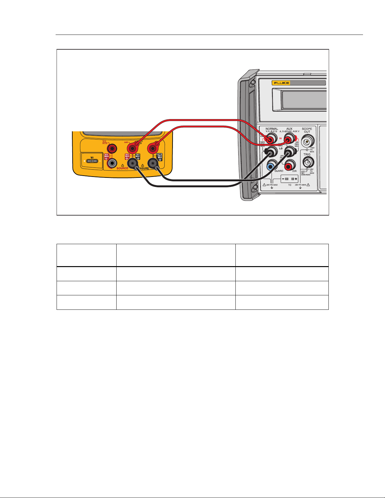
Figure 11. Four-Wire RTD Measure Verification Connections
Table 15. RTD Measure Verification (100W Pt (385), Four-Wire Connection)
Input °C
(Resistance)
1-Year ( °C ) 2-Year ( °C )
-180 °
(
27.096 Ω
)
-179.93 to -180.07 -179.86 to -180.14
100 °
(
138.505 Ω
)
99.93 to 100.07 99.86 to 100.14
780 ° (369.712 Ω) 779.79 to 780.21 779.59 to 780.41
RTD Measure, Three-Wire
Note
If a 5522A is not available, substitute a variable resistance source such as a
General Resistance RTD-100 RTD Simulator and a DMM to measure the
variable resistance source accurately. Use the resistance equivalents shown
in Table 16.
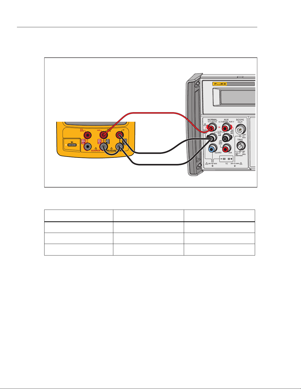
To verify the three-wire RTD measure function:
1. Connect the UUT to the 5522A as shown in Figure 12.
2. Set the UUT to the RTD measure function, Pt100 (385), ITS-90 scale, three-wire
termination.
3. Set the 5522A to RTD, Pt100 (385) at -180 °C, ITS-90 scale, and comp four-wire
to “OFF” position.
4. Set the 5522A to [Operate].
5. See if the value shown on the UUT is in the range shown in the applicable
column in Table 16.
753/754
Calibration Manual
28
6. Continue through the test points.
7. When you complete the test, set the 5522A to STANDBY.
5522A
CALIBRATOR
Fluke 75X
Fluke 5522A
gso14.eps
Figure 12. Three-Wire RTD Measure Verification Connections
Table 16. RTD Measure Verification (100W Pt (385), Three-Wire Connection)
Input °C (Resistance) 1-Year ( °C ) 2-Year ( °C )
-180 °
(
27.096 Ω
)
-179.53 to -180.47 -179.46 to -180.54
100 °
(
138.505 Ω
)
99.53 to 100.47 99.46 to 100.54
780 ° (369.712 Ω) 779.39 to 780.61 779.19 to 780.81

Documenting Process Calibrator
Performance Verification Tests
29
RTD Source
To verify the RTD Source function:
1. Connect the UUT to the 8508A DMM as shown in Figure 8. Use a four-wire
connection transitioning to two-wires at the UUT.
2. Set the 8508A to 4-Wire Ohms, auto-range.
3. Set the UUT to the RTD source function, Pt100 (385) at -180 °C, ITS-90 scale.
4. See if the value shown on the DMM is in the range shown in the applicable
column in Table 17.
5. Continue through the test points.
6. When you complete the test, push on the UUT two times to turn the source
function off. This conserves battery life.
Table 17. RTD Source Verification (100W Pt (385))
UUT
Output
Nominal (Ohms)
Minimum
1-Year
Maximum
1-Year
Minimum
2-Year
Maximum
2-Year
-180 °C 27.096 27.075 27.118 27.054 27.139
100 °C 138.505 138.487 138.524 138.468 138.543
780 °C 369.712 369.6707 369.7532 369.630 369.795