265ProFlow.pdf - 第18页
TECHNIC AL RE FERENCE MECHANICAL DETAIL 1.14 ProFlow Manual Chapter Issue 8 Dec 02 The transfer head is removable fr om the pressure mechanism unit. T wo locati ng dowels are used to sli de the unit onto the pre ssure me…
TECHNICAL REFERENCE
MECHANICAL DETAIL
Chapter Issue 8 Dec 02 ProFlow Manual 1.13
Cassette Transfer
Head
The function of the cassette transfer head option is to transfer print material from
the cassette unit and onto a board as ProFlow moves across the stencil.
The cassette type transfer head comprises the following:
• Conditioning Chamber (single or dual chamber)
• Cassette Carrier Unit
• 300mm Cassette
• Retention System (see Paste Retention System Figure for detail)
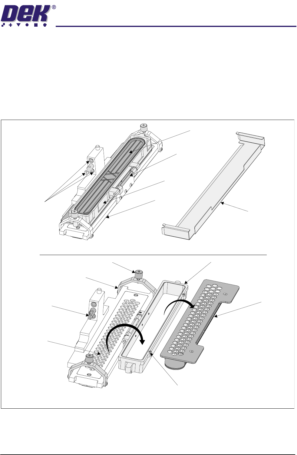
Figure 1-7 ProFlow Transfer Head
Pressure Mechanism
Locating Dowel
and Holes
Carrier Unit
Hinged
Bracket
Cassette
Conditioning
Chamber
Chassis Dowel
Carrier UnitThumbscrew (2 positions)
Clamp Bracket (2 positions)
Primary Grid
(removable)
ProFlow Transfer Head Assembly with Cover
Transfer Head Assembly Opened for Access
Cover
Cassette
Cassette Retaining Pin (2 positions)
TECHNICAL REFERENCE
MECHANICAL DETAIL
1.14 ProFlow Manual Chapter Issue 8 Dec 02
The transfer head is removable from the pressure mechanism unit. Two
locating dowels are used to slide the unit onto the pressure mechanism. Once
the unit is slid fully home, it is secured by closing the locking clip.
NOTE
When the transfer head is loaded with material, ensure that the cover is fitted
when the ProFlow unit is not in use. The cover must be removed prior to print
operation.
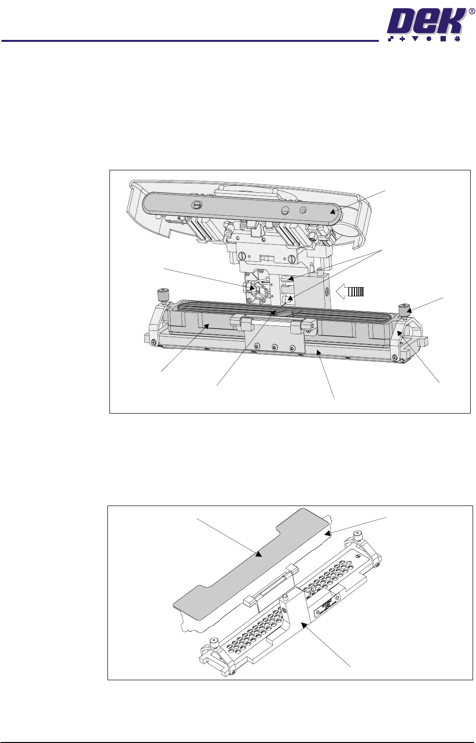
Figure 1-8 Transfer Head to Pressure Mechanism Interface
Transfer Head
Size Option
To enable the ProFlow to effectively print on wider boards, the cassette style
transfer head is supplied in three different size options of 300 mm; 350 mm; and
400 mm. The 300 mm size cassette is used with all of these options. (Transfer
Head Table in the Module Overview section refers.)
Figure 1-9 Transfer Head (350mm)
Pressure Mechanism
(raised position)
Locking Clip
Thumbscrew
(2 positions)
Carrier Unit
Cassette
Conditioning Chamber
Clamp Bracket
(2 positions)
Pressure Mechanism
Locating Dowels
(2 positions)
300mm Cassette
350mm Transfer Head Unit
Carrier Unit
TECHNICAL REFERENCE
MECHANICAL DETAIL
Chapter Issue 8 Dec 02 ProFlow Manual 1.15
Conditioning
Chamber
The ProFlow transfer head contains a conditioning chamber for maintaining the
condition of the print material. This chamber can be accessed by removing the
primary grid, which is accessible whilst the carrier unit is in the open position.
The grid is sealed onto the conditioning chamber by means of two M4 counter-
sunk screws and ‘O’ ring which fits into the transfer head (ProFlow Transfer
Head Figure refers). There are two types of conditioning chamber for both the
cassette carrier unit and rechargeable unit, as follows:
• Single Conditioning Chamber
• Dual Conditioning Chamber
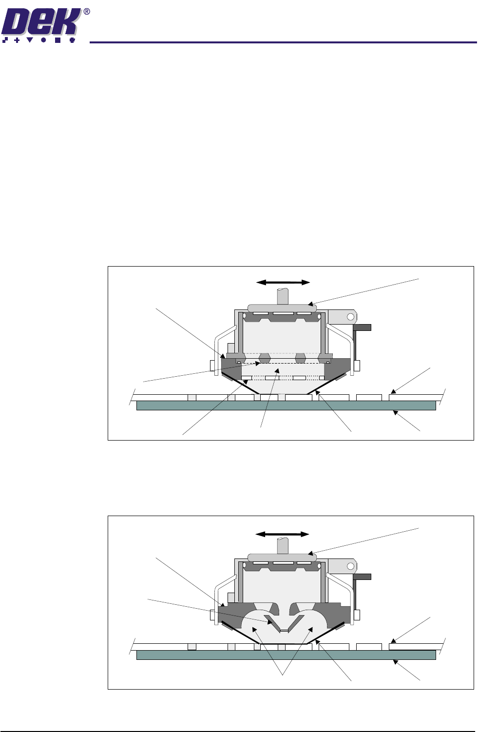
Single Conditioning
Chamber
The single conditioning chamber, ensures maximum print material optimization
on conventional SMT PCBs printing, the printing material is driven around the
conditioning chamber and bottom chamber by the action of the adhesive nature
of the printing material to the stencil, while the transfer head traverses the
image.
Dual Conditioning
Chamber
The dual conditioning chamber, was partly developed from knowledge gained
with the single conditioning chamber. This ensures maximum print material
transfer and optimization on more demanding process platforms, the print
material is driven around the two individual side chambers, in the same manner
as above.
Transfer
Head
Stencil
BoardWiper
ProFlow Movement (Y Axis)
Piston
Crosshead
Print Material
Conditioning Chamber
Secondary Grid
Primary
Grid
Transfer
Head
Stencil
BoardWiper
Piston
Crosshead
Side Chambers
Nozzle
ProFlow Movement (Y Axis)
Print Material