265ProFlow.pdf - 第42页
TECHNIC AL RE FERENCE POSITIONING 1.38 ProFlow Manual Chapter Issue 8 Dec 02 Cont act Height Contact height is when the ProFlow wipers are just in contact with the stencil, but wit h no force exerted (zero pressur e). NO…
TECHNICAL REFERENCE
POSITIONING
Chapter Issue 8 Dec 02 ProFlow Manual 1.37
POSITIONING ProFlow has four vertically positioned configurations:
• Home Position
• Zero Height
• Contact Height
• Print Height
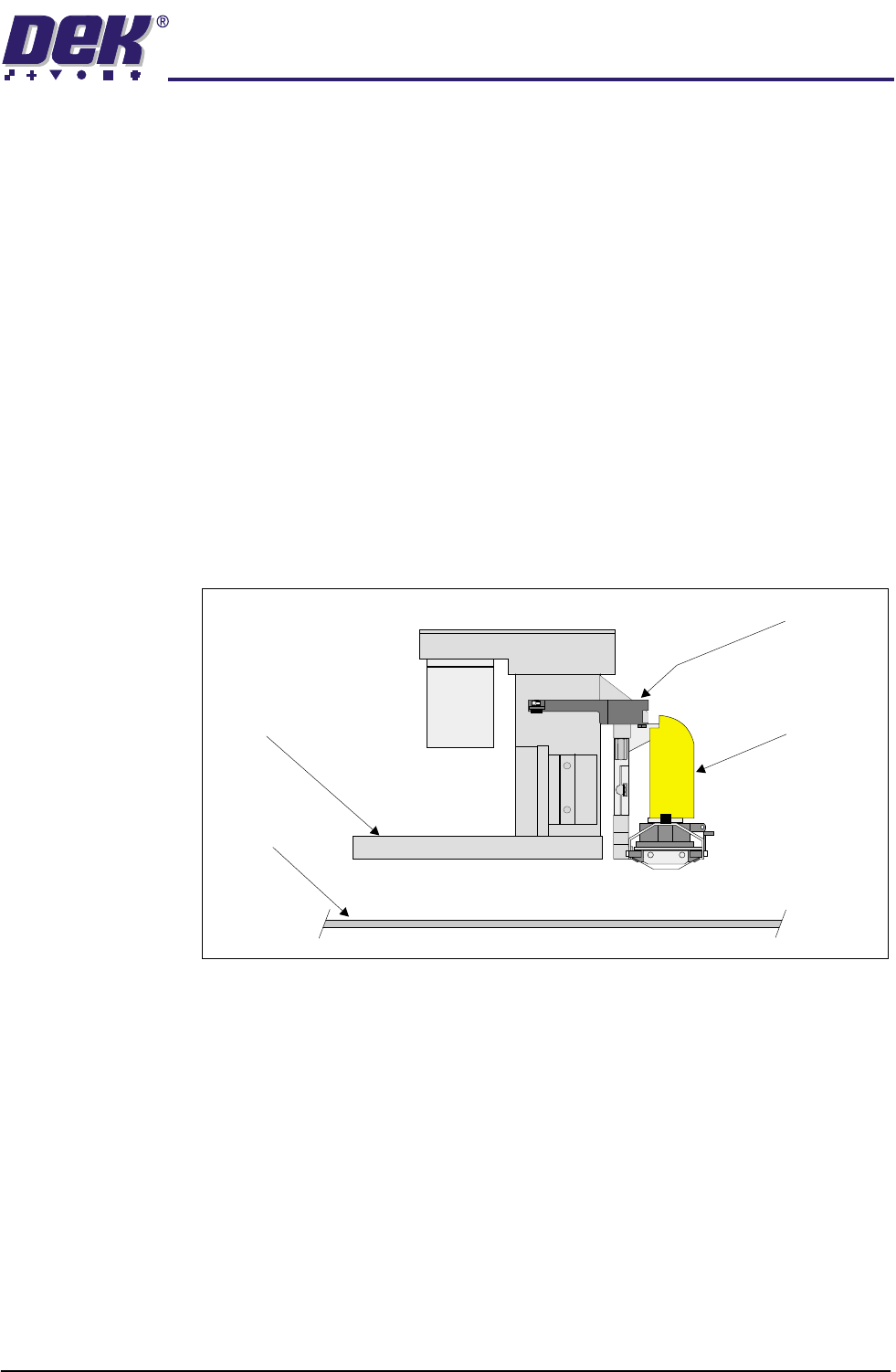
Home Position The home position is when the ProFlow unit is fully raised. The ProFlow unit is
homed on the following occasions:
• Initialization
• Power up
• Exiting diagnostics
• When power is restored following system power down.
NOTE
A downstop is not fitted to fixed head machines.
Figure 1-25 ProFlow in the Home Position
Zero Height The zero height position is when the ProFlow Unit is raised to the number of
steps on it’s internal counting system to move to the home position. The
ProFlow unit is moved to zero on the following occasions:
• Selecting Change ProFlow
• Selecting Change Screen
• Selecting Change Tooling
• Selecting Raise ProFlow
Stencil
ProFlow Unit
Downstop
Print Carriage
TECHNICAL REFERENCE
POSITIONING
1.38 ProFlow Manual Chapter Issue 8 Dec 02
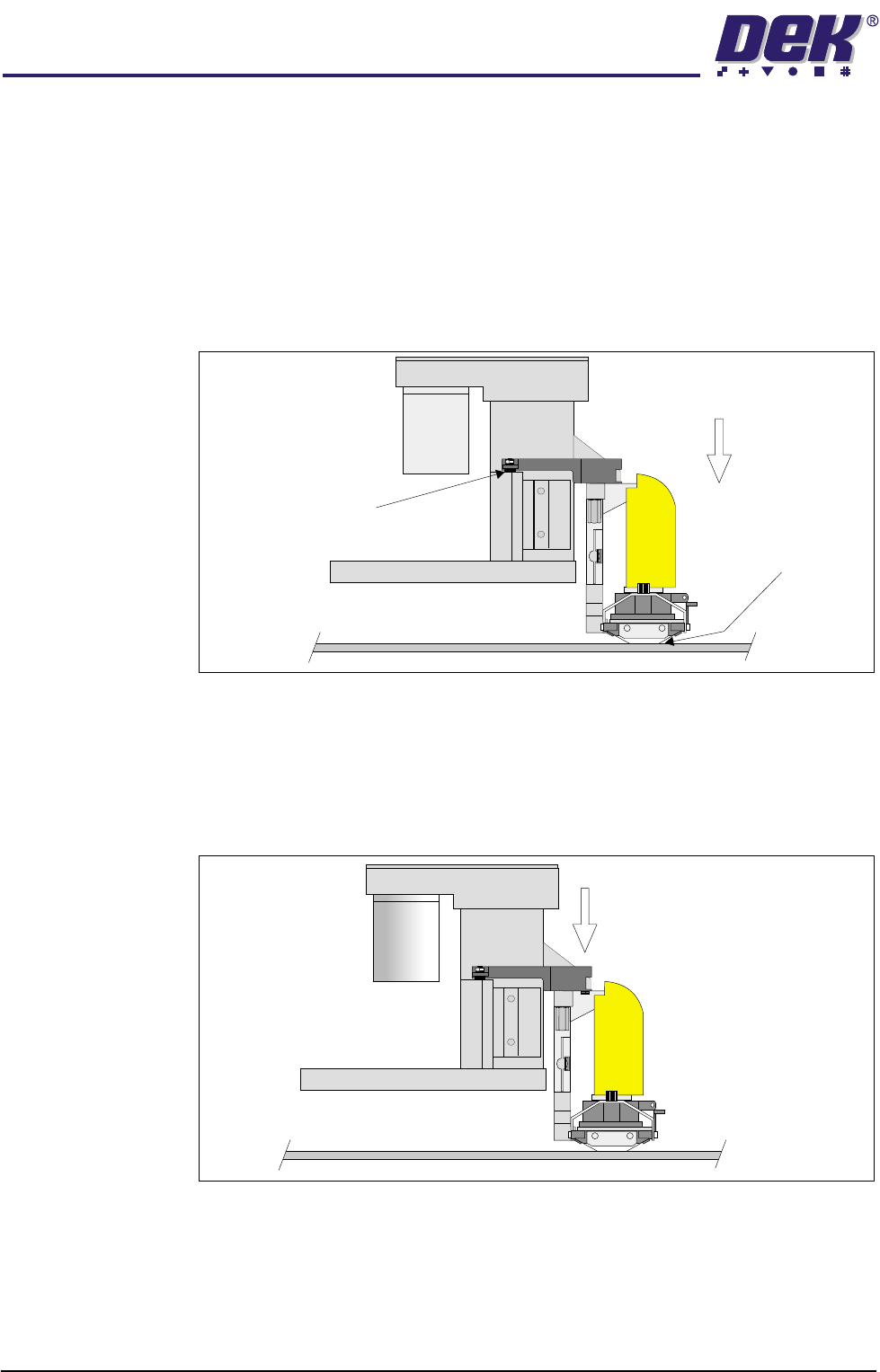
Contact Height Contact height is when the ProFlow wipers are just in contact with the stencil,
but with no force exerted (zero pressure).
NOTE
For setting up information refer to Contact Height Position Set Up in Calibrations
section of this chapter.
ProFlow should normally be left in this position when the unit is not in use, this
prevents material leakage, contact with the air/drying out and also prevents
material contamination.
Figure 1-26 ProFlow in the Contact Height Position
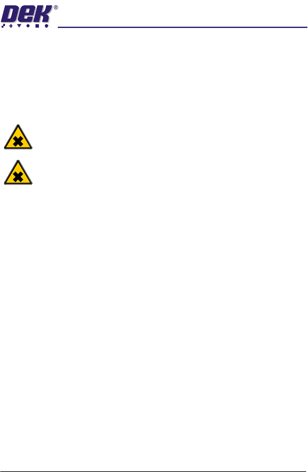
Print Height Print height is when the system pressure is being applied to ProFlow whilst
positioned on the stencil, (system pressure is dependent upon the board file
programmed). Piston pressure is also applied (during the print stroke) at this
position.
Figure 1-27 ProFlow in the Print Height Position
ProFlow Lowered
in Contact with Screen
Downstop in Contact
with Print Carriage
Zero Pressure
on Screen
ProFlow Lowered to
Print Height (System Pressure)
NOTE
Piston Pressure is applied
during the print cycle,
ie when the unit moves across
the stencil apertures.
TECHNICAL REFERENCE
ADJUSTMENTS AND SETTINGS
Chapter Issue 8 Dec 02 ProFlow Manual 1.39
ADJUSTMENTS AND SETTINGS
Cassette Low
Sensor
The cassette low sensor position can be changed in order to minimize print
material wastage. A graduated scale (millimetre) on the actuator cylinder body
provides a reference point for accurate sensor positioning, (Cassette Low
Sensor Adjustment figure refers). The sensor is moved up or down by loosen-
ing the securing screw, (1.5mm Allen key).
The factory setting for the sensor is set to 20mm on the graduated scale. Each
millimetre movement is equivalent to approximately 43gms of print material
usage.
WARNING
SOLDER PASTE AND SOLVENTS. WHEN USING OR HANDLING ANY SOLDER
PASTE OR SOLVENT FORMULATION THE MANUFACTURERS’ RECOMMEND
SAFETY PRECAUTIONS MUST BE STRICTLY ADHERED TO.
WARNING
PROTECTIVE CLOTHING. APPROVED PROTECTIVE CLOTHING SHOULD BE
WORN BY SOLDER PASTE AND SOLVENT HANDLERS AT ALL TIMES TO
ELIMINATE FUME INHALATION, EYE CONTACT, SKIN CONTACT AND
INGESTION.
The following procedure should be carried out when print material wastage is
excessive.
1. Gain access to the ProFlow unit by opening the machine cover.
2. Lift off the ProFlow pressure mechanism cover.
Cassette Option 3. Noting the present position of the sensor against the graduated marker,
loosen the sensor using a 1.5mm Allen key.
4. With each graduation on the graduation scale being equivalent to approxi-
mately 43gms of print material, move the sensor down by single graduations
until the optimum print material usage position is obtained, (Cassette Low
Sensor Adjustment figure refers).
5. Carefully re-tighten the sensor securing screw.
NOTE
To prevent damage to the sensor, do not overtighten grub screw.
6. Replace the pressure mechanism cover.
7. Close the machine cover.
Rechargeable
Transfer Head
Option
8. When using a rechargeable transfer head and paste low sensor activation
is required at the mid diaphragm point the reed sensor can be inverted so
that a higher sensor initiation can be achieved. (In this position the sensor
cable is at the bottom of the sensor.)