265ProFlow.pdf - 第54页
TECHNIC AL RE FERENCE REPLACEM ENT PROCED URES 1.50 ProFlow Manual Chapter Issue 8 Dec 02 remove the mechanism out of the print carriage. Remove to safe stowage. 6. Position the ProFlow printhead mec hanism locating dowe…

TECHNICAL REFERENCE
REPLACEMENT PROCEDURES
Chapter Issue 8 Dec 02 ProFlow Manual 1.49
• Clean After Knead
• Knead After Replenish
If Advanced ProFlow is set to enabled, adjust the following ProFlow param-
eters as appropriate:
• FWD Start Speed
• FWD End Speed
• RWD Start Speed
• RWD End Speed
• FWD Start Pressure
• FWD End Pressure
• RWD Start Pressure
• RWD End Pressure
If Advanced ProFlow is set to disabled, adjust the following ProFlow param-
eters as appropriate:
• Front Print Speed
• Rear Print Speed
• Print Paste Pressure
NOTE
Information on the ProFlow parameters are detailed under Menu Parame-
ters in the Machine Programming chapter of the User manual.
Information on the machine set up procedures are detailed in the Machine
Programming chapter of the User manual.
Squeegees to
ProFlow (Fixed
Head Machines)
Instances may occur when the machine is required to print using the ProFlow
module configuration. The following procedure details how to revert the
machine from squeegee use to the ProFlow configuration:
ProFlow Printhead
Mechanism
1. In Diagnostics ensure that the squeegees are homed. Position the print
carriage so that removal and fit is carried out within easy reach.
2. Switch the machine OFF and disconnect pneumatics.
3. If squeegees are fitted, remove to a safe stowage.
4. Remove the following squeegee mechanism connectors from the print
carriage, right hand side:
• 9PL16 - Front squeegee motor
• 9PL17 - Rear squeegee motor
• 9PL08 - Front and rear home sensors
• 9PL19 - Pressure amplifier (if fitted)
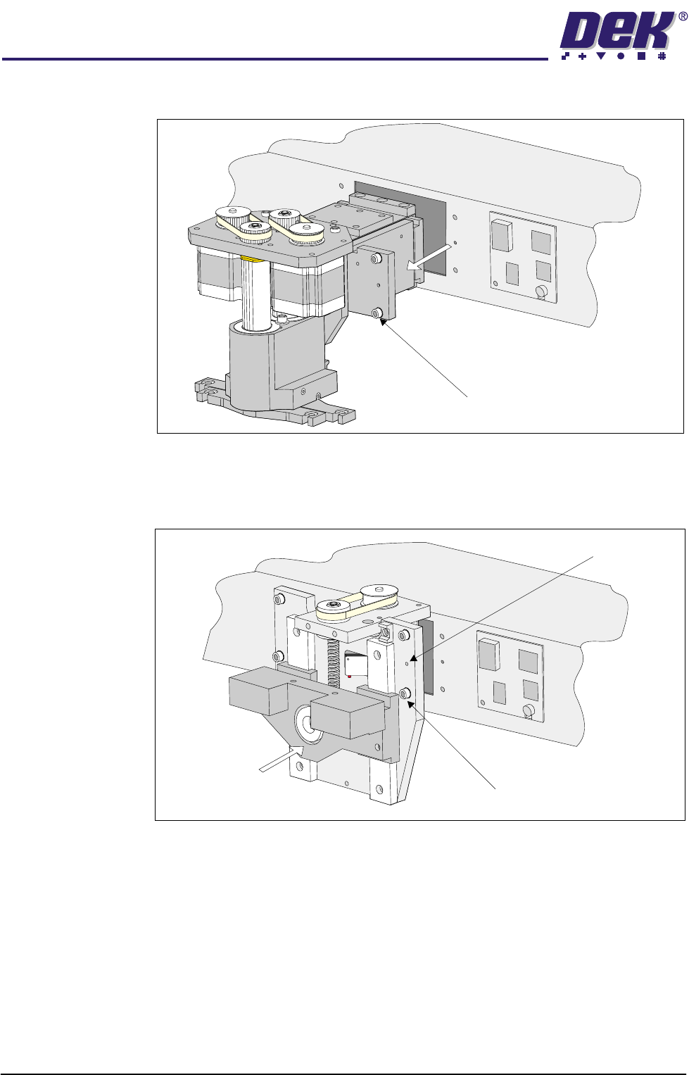
5. Loosen the four captive screws securing the squeegee printhead mecha-
nism to the print carriage, using a 4mm Allen key (figure refers). Carefully
TECHNICAL REFERENCE
REPLACEMENT PROCEDURES
1.50 ProFlow Manual Chapter Issue 8 Dec 02
remove the mechanism out of the print carriage. Remove to safe stowage.
6. Position the ProFlow printhead mechanism locating dowels into the print
carriage and secure the unit by means of the four captive screws, using a
4mm Allen key (see figure below).
7. Fit the following ProFlow mechanism connectors (figure refers):
• ProFlow motor connector 9PL17 into 9 way socket 9SK17
• ProFlow home sensor connector 9PL08 into 6 way socket 9SK08
Captive Screw (4 positions)
Captive Screw (4 positions)
Locating Dowels (2 Positions)
TECHNICAL REFERENCE
REPLACEMENT PROCEDURES
Chapter Issue 8 Dec 02 ProFlow Manual 1.51
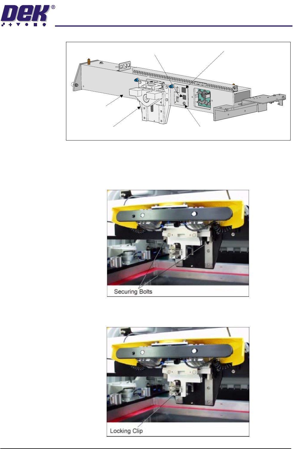
ProFlow Unit 1. Fit the pressure mechanism part of the ProFlow unit to the ProFlow print-
head mechanism bearing block by means of the two securing bolts. Tighten
using a 5mm Allen key.
NOTE
Unit shown in unlatched position to identify bolts.
2. Ensure that the locking clip on the pressure mechanism is pressed over to
the right and clicks into place, as shown in the figure below. This ensures
that the locking clip is in the correct position to secure the transfer head.
Print Carriage
ProFlow (Printhead) Mechanism
9SK08 (Home Sensor)
ProFlow Fitted Socket
9SK17 (ProFlow Motor)