265ProFlow.pdf - 第35页
TECHNI CAL REFEREN CE DRI VES AND SE NSOR S Chapter Issue 8 Dec 02 ProFlow Manual 1.31 Cassette L ow Sensor When the p aste reservoir bec omes low or empty of pri nt mater ial, t he sensor operates givi ng a warning win …
TECHNICAL REFERENCE
DRIVES AND SENSORS
1.30 ProFlow Manual Chapter Issue 8 Dec 02
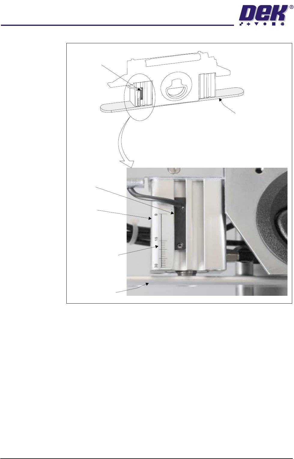
Figure 1-22 Cassette Low Sensor Location
15
0
30
Pressure Mechanism (cover removed)
Sensor Unit
Piston Crosshead
Piston Crosshead
Graduated Marker
Actuator
Reed Sensor
TECHNICAL REFERENCE
DRIVES AND SENSORS
Chapter Issue 8 Dec 02 ProFlow Manual 1.31
Cassette Low
Sensor
When the paste reservoir becomes low or empty of print material, the sensor
operates giving a warning window on the machine monitor and the indication of
the tricoloured beacon is changed.
NOTE
Selecting Warn, Pause or Suspend in Set Preferences (Consumable Action)
affects the machine reaction to a Cassette Low indication. Refer to the Set
Preferences and Consumable Replenishments chapters of the machine manual
for more details.
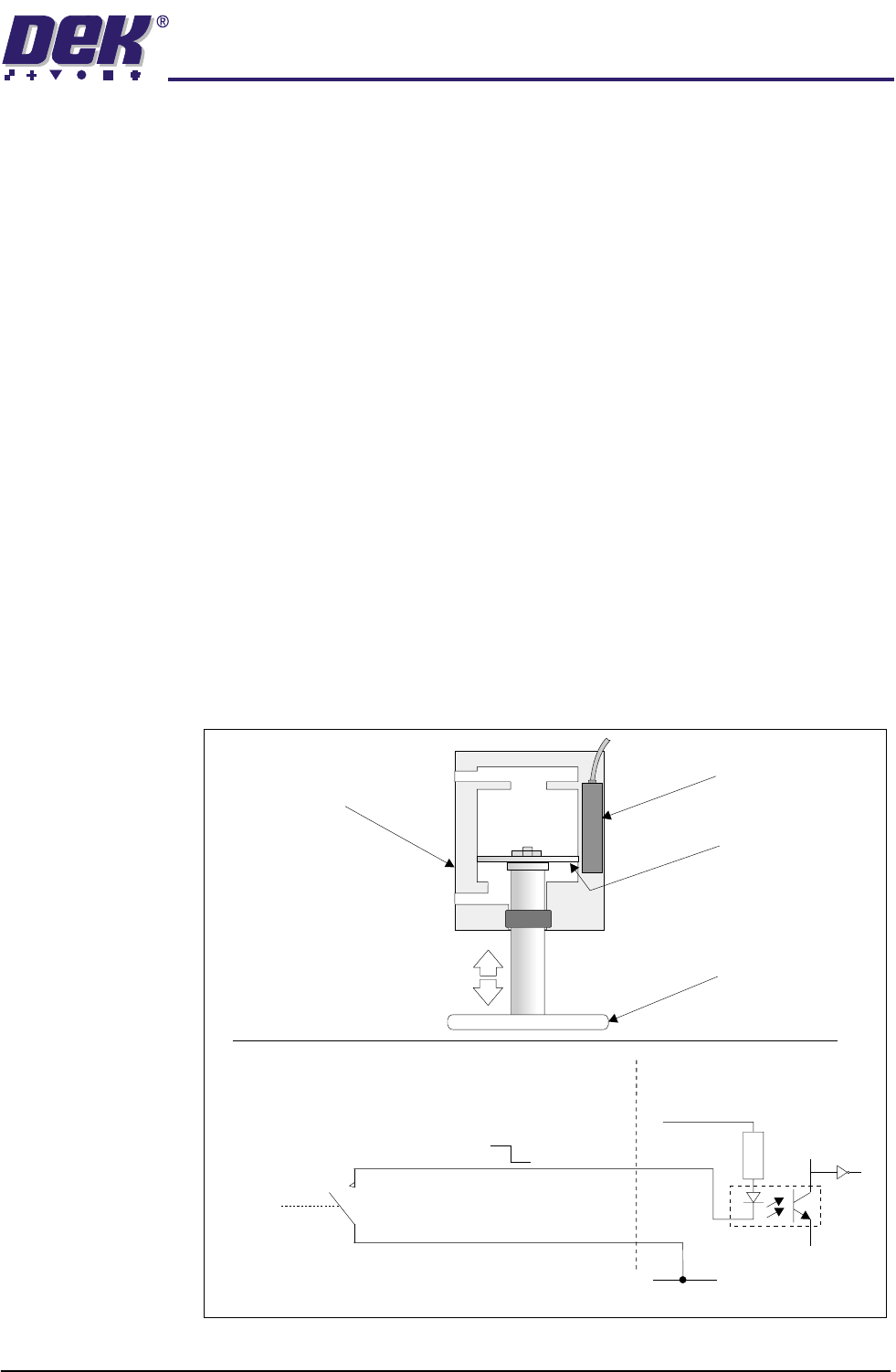
The cassette low sensor reed switch is secured to the left pneumatic actuator
on the ProFlow pressure mechanism, (Cassette Low Sensor Location refers).
The pneumatic actuator pistons move slowly down as the print medium inside
the transfer head is used up. The sensor reed switch is enabled when the
magnetized piston diaphragm comes into close proximity with it, (Reed Switch
and Circuit Schematic figure below refers).
The input for the cassette low sensor floats high until the reed switch is enabled,
once made the input is pulled down to 0v. This information is fed to the
PCADADIO card within Y3 enclosure for GSX and Lt machines and the Multi-
Move X12 card (IN6) of the machine controller for Infinity and fixed head
machines.
NOTE
The cassette low sensor is height adjustable so that print material wastage can
be reduced to a minimum. For further information refer to the Adjustments and
Settings section of this chapter.
Figure 1-23 Reed Switch and Circuit Schematic
Reed Switch and Circuit Schematic
Digital Input
to MultiMove x12
V+ (User)
Opto-isolator
(Red)
(Black)
2K
0V
12V
0V
N0
(normally open)
Reed Switch
Piston Diaphragm
(magnetized)
Piston Crosshead
Pressure
Actuator
(cutaway view)
Direction of
Piston
Movement

TECHNICAL REFERENCE
SEQUENCES
1.32 ProFlow Manual Chapter Issue 8 Dec 02
SEQUENCES
Print Cycle ProFlow is a single bi-directional printing device, there is no requirement (with
the exception of knead paste), to carry out any vertical movements at the end
of each print stroke.
Contact Height 1. At the start of the print cycle the ProFlow unit is lowered to contact height
(zero pressure) onto the screen, Step 1 of ProFlow Print Cycle figure refers.
NOTE
When the unit is on the screen, the paste pressure is at Idle Paste Pressure.
The print carriage is positioned to ensure that when the rising table is lifted
the ProFlow wipers are positioned directly over the front or rear rail board
clamps.
System Pressure 2. System pressure is applied to the ProFlow unit prior to the print carriage
commencing the print stroke (ProFlow print height), Step 2 of ProFlow Print
Cycle Figure refers.
NOTE
System pressure is the force exerted by ProFlow (utilizing the squeegee
stepper motors or ProFlow printhead stepper motor) onto the stencil during
the print cycle.
A downward force of approximately 3 kilograms is found to be suitable for a
300mm size ProFlow unit.
Paste Pressure 3. A Print Paste Pressure of approximately 2 bar is applied to the ProFlow
transfer head during the print stroke, Step 3 of ProFlow Print Cycle Figure
refers.
NOTE
If Advanced ProFlow is enabled, Print Paste Pressure is replaced by a start
and end pressure in both forward and rearward print directions.
4. The print carriage performs a print stroke at a speed of between 2 - 150mm/
sec (75mm/sec nominal), Step 3 of ProFlow Print Cycle Figure refers. Print
Paste Pressure is removed from the transfer head on completion of the print
stroke (and before system pressure is removed).
NOTE
If Fast Print Speed is enabled the maximum speed is increased from
150mm/sec to 300mm/sec.
5. The print carriage stops at a position centrally on a rail, ensuring that
ProFlow is well supported whilst still under system pressure.
6. The system pressure is removed returning the ProFlow unit to contact height
(zero pressure). Step 4 of ProFlow Print Cycle Figure refers.
ProFlow is now ready to print the next board by repeating the above sequence
whilst travelling in the alternate direction.
NOTE
When printing has finished, the unit can be left on the screen in its contact
position and the print material remains sealed to the atmosphere. If the ProFlow
unit is not to be utilized for a prolonged period of time, it should be separated
from the screen and the cover fitted.