265ProFlow.pdf - 第22页
TECHNIC AL RE FERENCE MECHANICAL DETAIL 1.18 ProFlow Manual Chapter Issue 8 Dec 02 Retention System The retent ion system, is sited on t he unders ide of t he transfer head and consist s of: • Secondary Gri d - st ainles…
TECHNICAL REFERENCE
MECHANICAL DETAIL
Chapter Issue 8 Dec 02 ProFlow Manual 1.17
The specially designed ProFlow cassette makes loading of the print material
rapid and user friendly. The cassette system reduces waste to an absolute
minimum and is also environmentally friendly (the operator does not have to
touch or manually work print material at any stage during print operations).
The routine for changing cassettes is detailed in the Consumable Replenish-
ments chapter of the machine manual.
ProFlow cassettes are supplied hermetically sealed with a tear off foil, this is
removed after the cassette has been fitted to the ProFlow transfer head. If the
cassette is being fitted to a new or cleaned transfer head, ie where the transfer
head conditioning chamber is free from print material. The ProFlow unit should
be primed as detailed in the Consumable Replenishments chapter of the
machine manual before print operations are carried out.
When the cassette is fitted to the ProFlow unit the system is totally enclosed,
maintaining the print material in optimum condition. If the system has not been
used for some time a knead operation is available, as detailed in the Sequences
- Knead Paste section of this chapter.
A cover can be fitted to the underside of the transfer head during periods when
the ProFlow unit is in the raised position or if the transfer head is removed.
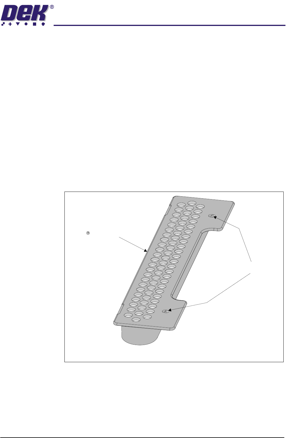
Figure 1-11 ProFlow Cassette
Semco Cassette
Retaining Pin Recesses
Cassette Shown with Sealing Strip Removed
TECHNICAL REFERENCE
MECHANICAL DETAIL
1.18 ProFlow Manual Chapter Issue 8 Dec 02
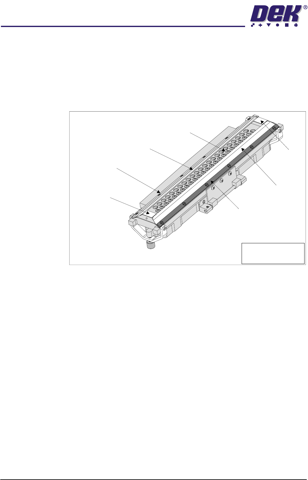
Retention System The retention system, is sited on the underside of the transfer head and consists
of:
• Secondary Grid - stainless steel (Single Conditioning Chamber Units only)
• Wipers - 200/300 titanium coated step edged (2 positions)
• Skis - Vulcanized Rubber (2 positions)
• Wiper Retaining Strips (2 positions)
Figure 1-12 Retention System
Maintenance In order to maintain and clean the unit, all items of the retention system can be
easily dismantled. Wipers and skis are inevitably prone to wear over prolonged
use.
300 micron titanium wipers are available where additional ProFlow system
pressure transfer is required. These are available for all transfer head sizes.
For ink/adhesive printing, mylar wipers are available for all transfer head sizes.
A specially designed transfer head maintenance stand is supplied with ProFlow
to be used during cleaning and maintenance operations of the retention system.
Information on the removal and replacement of these items is detailed in the
Consumable Replenishments chapter of the machine manual.
Wiper
Secondary Grid (Stainless Steel)
Wiper
Wiper Retaining Strip
Wiper Retaining Strip
Ski
Ski
Transfer Head Inverted
Note
Single conditioning unit
type transfer head.
TECHNICAL REFERENCE
MECHANICAL DETAIL
Chapter Issue 8 Dec 02 ProFlow Manual 1.19
Rechargeable
Transfer Head
The rechargeable transfer head option is fully compatible with the ProFlow
hardware and offers the alternative of using ProFlow without changing the
format new material is supplied in, ie material not in ProFlow cassettes can still
be used with ProFlow.
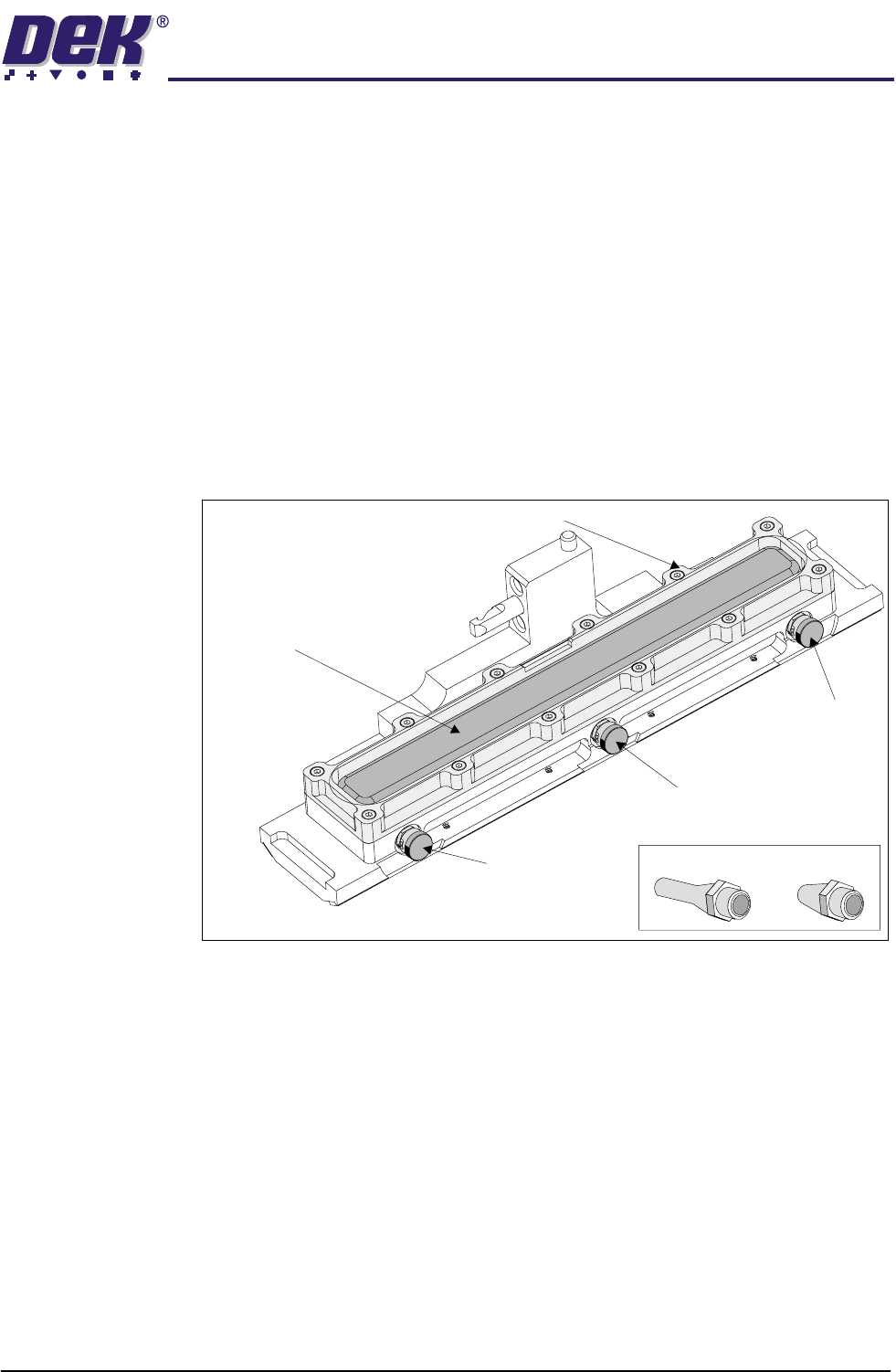
Elements of the rechargeable transfer head comprise:
• Conditioning Chamber (single or dual chamber)
• Diaphragm Retainer
• Diaphragm
• Filling Ports (3 in number, 1 for 150mm transfer head)
• Retention System
• Cover
• Recharging Nozzles (2 in number)
Figure 1-13 Rechargeable Transfer Head
The rechargeable transfer head is constructed in much the same way as the
cassette transfer head. The main difference being that a diaphragm, held in
position by a diaphragm retainer, replaces the cassette. The transfer head is
fitted to the pressure mechanism unit in the same way as the cassette transfer
head unit, (Cassette Transfer Head section of this chapter refers).
Print material is initially filled into the paste chamber through the stainless steel
grid of the retention system (single conditioning chamber units), or the nozzle
system of the dual conditioning chamber type. General recharging is performed
by using the 3 filling ports sited on the front side of the transfer head. The filling
ports are sealed using bayonet connector caps.
NOTE
For detailed procedures of print material filling refer to the Consumable Replen-
ishments chapter of the machine manual or the ProFlow Best Working Practices
guide (DEK Part No. 171280).
Filling Port
Bayonet Cap
Diaphragm
Diaphragm Retainer
Recharging Nozzles
Filling Port
Bayonet Cap
Filling Port
Bayonet Cap
Transfer Head (Showing Diaphragm)