265ProFlow.pdf - 第37页
TECHNI CAL REFEREN CE SEQUEN CES Chapter Issue 8 Dec 02 ProFlow Manual 1.33 Figure 1-24 Side View of ProFlow During Print Cycle Print Paste Pressure System Pressure Board Clamp (2 positions) Board S tencil Print Carriage…

TECHNICAL REFERENCE
SEQUENCES
1.32 ProFlow Manual Chapter Issue 8 Dec 02
SEQUENCES
Print Cycle ProFlow is a single bi-directional printing device, there is no requirement (with
the exception of knead paste), to carry out any vertical movements at the end
of each print stroke.
Contact Height 1. At the start of the print cycle the ProFlow unit is lowered to contact height
(zero pressure) onto the screen, Step 1 of ProFlow Print Cycle figure refers.
NOTE
When the unit is on the screen, the paste pressure is at Idle Paste Pressure.
The print carriage is positioned to ensure that when the rising table is lifted
the ProFlow wipers are positioned directly over the front or rear rail board
clamps.
System Pressure 2. System pressure is applied to the ProFlow unit prior to the print carriage
commencing the print stroke (ProFlow print height), Step 2 of ProFlow Print
Cycle Figure refers.
NOTE
System pressure is the force exerted by ProFlow (utilizing the squeegee
stepper motors or ProFlow printhead stepper motor) onto the stencil during
the print cycle.
A downward force of approximately 3 kilograms is found to be suitable for a
300mm size ProFlow unit.
Paste Pressure 3. A Print Paste Pressure of approximately 2 bar is applied to the ProFlow
transfer head during the print stroke, Step 3 of ProFlow Print Cycle Figure
refers.
NOTE
If Advanced ProFlow is enabled, Print Paste Pressure is replaced by a start
and end pressure in both forward and rearward print directions.
4. The print carriage performs a print stroke at a speed of between 2 - 150mm/
sec (75mm/sec nominal), Step 3 of ProFlow Print Cycle Figure refers. Print
Paste Pressure is removed from the transfer head on completion of the print
stroke (and before system pressure is removed).
NOTE
If Fast Print Speed is enabled the maximum speed is increased from
150mm/sec to 300mm/sec.
5. The print carriage stops at a position centrally on a rail, ensuring that
ProFlow is well supported whilst still under system pressure.
6. The system pressure is removed returning the ProFlow unit to contact height
(zero pressure). Step 4 of ProFlow Print Cycle Figure refers.
ProFlow is now ready to print the next board by repeating the above sequence
whilst travelling in the alternate direction.
NOTE
When printing has finished, the unit can be left on the screen in its contact
position and the print material remains sealed to the atmosphere. If the ProFlow
unit is not to be utilized for a prolonged period of time, it should be separated
from the screen and the cover fitted.
TECHNICAL REFERENCE
SEQUENCES
Chapter Issue 8 Dec 02 ProFlow Manual 1.33
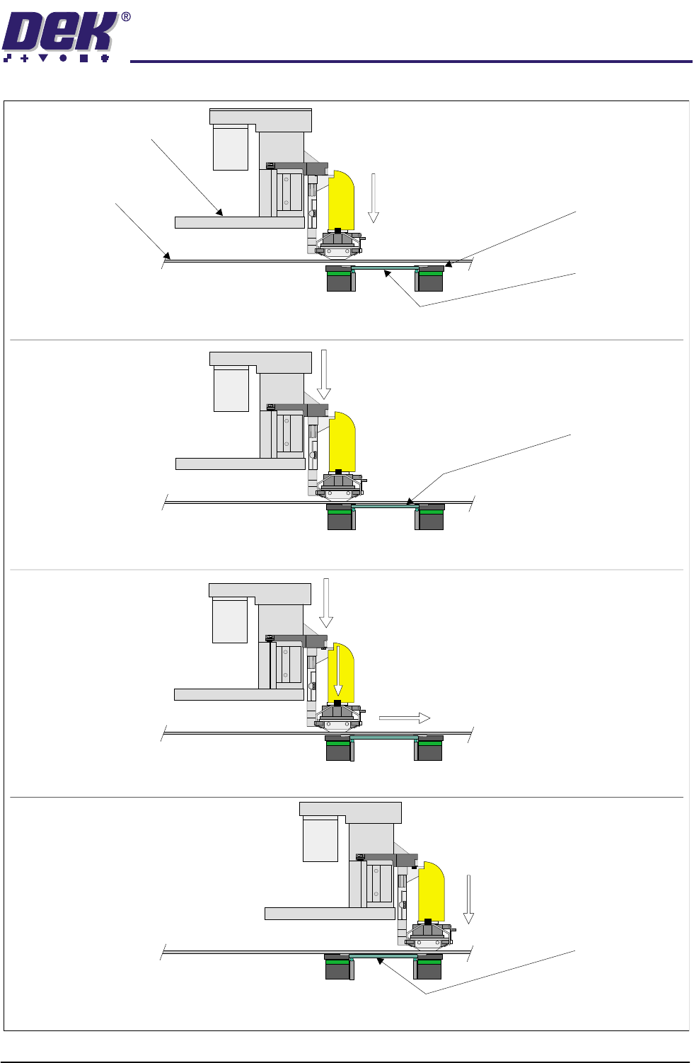
Figure 1-24 Side View of ProFlow During Print Cycle
Print Paste Pressure
System Pressure
Board Clamp
(2 positions)
Board
Stencil
Print Carriage
Step 1 - ProFlow Moved to Contact Height with Stencil
Step 3 - Print Paste Pressure Applied During Print Stroke
Step 2 - System Pressure Applied Prior to Printing (Print Height)
Step 4 - Print Paste Pressure Followed by System Pressure Removed at End of Print Stroke
Print Carriage Movement
Contact Height
(Zero Pressure)
System Pressure
Printed Board
Contact Height
(Zero Pressure)
Board (raised
to print height)

TECHNICAL REFERENCE
SEQUENCES
1.34 ProFlow Manual Chapter Issue 8 Dec 02
ProFlow
Placement
This sequence is designed to move the ProFlow unit from the home or zero
height position onto the stencil, at contact height, when one of the following
occurs:
• When Run is selected.
• When Knead Paste is selected.
• When Prime ProFlow is selected
• When Refill ProFlow is selected.
Raise ProFlow This sequence is designed to move the ProFlow unit from the stencil to the
home or zero height position when one of the following occurs:
• When the machine is initialized.
• When Change ProFlow is selected.
• When Change Screen is selected.
• When Change Tooling is selected.
• When Raise ProFlow is selected.
The ProFlow unit is raised by one of the following methods:
• 'Shake-off' ProFlow
• 'Lift-off' ProFlow
Shake-off is the preferred method of raising the ProFlow unit. Lift-off is only
carried out if the ProFlow unit is not in a shake-off envelope or the stencil
protection parameter in the board file is set to ON.
The shake-off envelope is the portion of stencil required by the ProFlow transfer
head when performing the shake-off or knead over rail function. Depending on
the stencil, it’s justification and the board width, a particular product may have
none, one or two shake-off envelopes. If the unit is not in a shake-off envelope
a lift-off is carried out.
Shake-off ProFlow This sequence is designed to raise the ProFlow unit clear of the stencil without
leaving a print medium deposit on the stencil. Pre-conditions exist prior to any
shake-off procedure, these are:
• The ProFlow unit is on the stencil at contact height.
• The pressure on the transfer material is at Idle Paste Pressure or else it is
released.
• The ProFlow unit is inside a valid shake-off envelope.
• The printers cover is closed.
• The stencil protection parameter in the board file is set to OFF.
The following sequence occurs when shake-off is initiated:
1. The machine cover is secured while the shake-off is carried out.
2. Any pressure on the transfer material is released.
3. The board clamps are closed.
4. The camera is driven home and the rising table is raised to print height.