265ProFlow.pdf - 第55页
TECHNI CAL REFEREN CE REPLACEM ENT PROC EDURES Chapter Issue 8 Dec 02 ProFlow Manual 1.51 ProFlow Unit 1. Fit the pressure mechani sm part of t he ProFlow unit t o the ProFlow pr int- head mechanis m bearing block by mea…
TECHNICAL REFERENCE
REPLACEMENT PROCEDURES
1.50 ProFlow Manual Chapter Issue 8 Dec 02
remove the mechanism out of the print carriage. Remove to safe stowage.
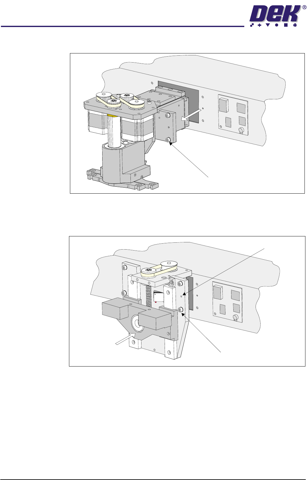
6. Position the ProFlow printhead mechanism locating dowels into the print
carriage and secure the unit by means of the four captive screws, using a
4mm Allen key (see figure below).
7. Fit the following ProFlow mechanism connectors (figure refers):
• ProFlow motor connector 9PL17 into 9 way socket 9SK17
• ProFlow home sensor connector 9PL08 into 6 way socket 9SK08
Captive Screw (4 positions)
Captive Screw (4 positions)
Locating Dowels (2 Positions)
TECHNICAL REFERENCE
REPLACEMENT PROCEDURES
Chapter Issue 8 Dec 02 ProFlow Manual 1.51
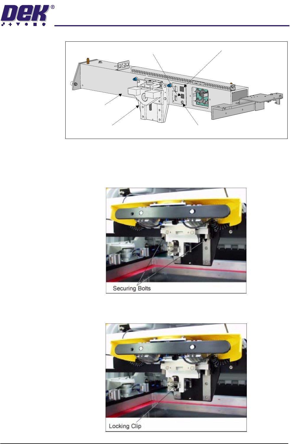
ProFlow Unit 1. Fit the pressure mechanism part of the ProFlow unit to the ProFlow print-
head mechanism bearing block by means of the two securing bolts. Tighten
using a 5mm Allen key.
NOTE
Unit shown in unlatched position to identify bolts.
2. Ensure that the locking clip on the pressure mechanism is pressed over to
the right and clicks into place, as shown in the figure below. This ensures
that the locking clip is in the correct position to secure the transfer head.
Print Carriage
ProFlow (Printhead) Mechanism
9SK08 (Home Sensor)
ProFlow Fitted Socket
9SK17 (ProFlow Motor)
TECHNICAL REFERENCE
REPLACEMENT PROCEDURES
1.52 ProFlow Manual Chapter Issue 8 Dec 02
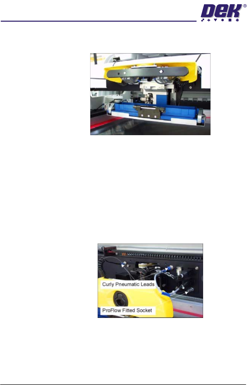
3. Locate and fit the ProFlow transfer head unit to the pressure mechanism by
means of the two locating dowels. Slide the unit onto the pressure mecha-
nism. Once the unit is slid fully home, it is secured by closing the locking clip.
4. Lift the light shroud for access (if fitted) and plug the electrical connection
ProFlow Fitted from the ProFlow unit into the socket sited on the right hand
side of the ProFlow on the print carriage, (figure below refers).
CAUTION
ELECTRICAL CONNECTION.
This electrical connection informs the
machine of ProFlow fitment and must always be connected whilst the
ProFlow unit is fitted otherwise damage may occur if machine is run.
Connect the curly pneumatic leads from the pressure mechanism to each
respective left and right pneumatic connector sited either side of the ProFlow
printhead mechanism (figure below refers).
NOTE
If the squeegee paste dispenser option is fitted to the print carriage, before
using ProFlow, ensure that the paste dispenser regulator gauge reads '0'
pressure.
5. Connect the pneumatics and switch the machine to ON. To ensure that the
machine recognizes the ProFlow module, the following indications on the
machine MMI are evident:
a. During the boot up sequence the operator is prompted to fit the ‘ProFlow
cover’.
b. The soft key that previously indicated ‘Paste Load’ now indicates
‘Knead Paste’.