265ProFlow.pdf - 第53页
TECHNI CAL REFEREN CE REPLACEM ENT PROC EDURES Chapter Issue 8 Dec 02 ProFlow Manual 1.49 • Clean Aft er Knead • Knead After Replenish If Advan ced ProFlow i s set t o enabl ed, adjust the fol lowin g ProFlow p aram- ete…
TECHNICAL REFERENCE
REPLACEMENT PROCEDURES
1.48 ProFlow Manual Chapter Issue 8 Dec 02
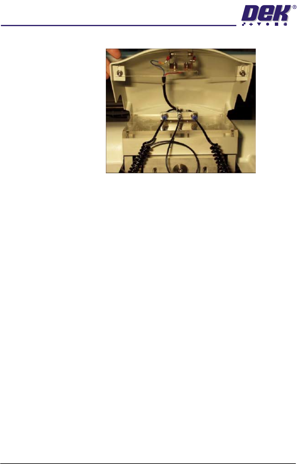
tive left and right connector.
10. Connect the pneumatics and switch the machine to ON. To ensure that the
machine recognizes the ProFlow module, the following indications on the
machine MMI are evident:
a. During the boot up sequence the operator is prompted to fit the ‘ProFlow
cover’.
b. The soft key that previously indicated ‘Paste Load’ now indicates
‘Knead Paste’.
c. In Diagnostics the ProFlow menu page can be accessed.
11. Carry out the ProFlow Contact Position Setup in the Calibrations section
later in this chapter.
12. Select Setup on the MMI. Select Load Data and load the product file to be
printed.
NOTE
For an existing product, the product file has already been written. If the
product is new, either edit an existing or default file. (The Machine Program-
ming Chapter of the User Manual refers.)
13. If the loaded file is the correct file for the product this completes Squeegees
to ProFlow Replacement. If the loaded file has to be edited, proceed with
Step 14.
14. Select Edit Data on the MMI and adjust the following ProFlow parameters
as appropriate:
• Transfer Head Size
• Stencil Protection
• System Pressure
• Idle Paste Pressure
• Knead Paste Pressure
• Knead Off-image
• Knead Before Print

TECHNICAL REFERENCE
REPLACEMENT PROCEDURES
Chapter Issue 8 Dec 02 ProFlow Manual 1.49
• Clean After Knead
• Knead After Replenish
If Advanced ProFlow is set to enabled, adjust the following ProFlow param-
eters as appropriate:
• FWD Start Speed
• FWD End Speed
• RWD Start Speed
• RWD End Speed
• FWD Start Pressure
• FWD End Pressure
• RWD Start Pressure
• RWD End Pressure
If Advanced ProFlow is set to disabled, adjust the following ProFlow param-
eters as appropriate:
• Front Print Speed
• Rear Print Speed
• Print Paste Pressure
NOTE
Information on the ProFlow parameters are detailed under Menu Parame-
ters in the Machine Programming chapter of the User manual.
Information on the machine set up procedures are detailed in the Machine
Programming chapter of the User manual.
Squeegees to
ProFlow (Fixed
Head Machines)
Instances may occur when the machine is required to print using the ProFlow
module configuration. The following procedure details how to revert the
machine from squeegee use to the ProFlow configuration:
ProFlow Printhead
Mechanism
1. In Diagnostics ensure that the squeegees are homed. Position the print
carriage so that removal and fit is carried out within easy reach.
2. Switch the machine OFF and disconnect pneumatics.
3. If squeegees are fitted, remove to a safe stowage.
4. Remove the following squeegee mechanism connectors from the print
carriage, right hand side:
• 9PL16 - Front squeegee motor
• 9PL17 - Rear squeegee motor
• 9PL08 - Front and rear home sensors
• 9PL19 - Pressure amplifier (if fitted)
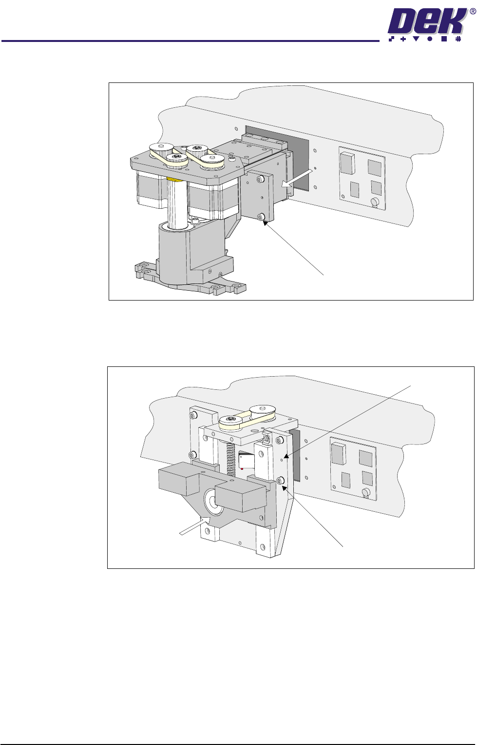
5. Loosen the four captive screws securing the squeegee printhead mecha-
nism to the print carriage, using a 4mm Allen key (figure refers). Carefully
TECHNICAL REFERENCE
REPLACEMENT PROCEDURES
1.50 ProFlow Manual Chapter Issue 8 Dec 02
remove the mechanism out of the print carriage. Remove to safe stowage.
6. Position the ProFlow printhead mechanism locating dowels into the print
carriage and secure the unit by means of the four captive screws, using a
4mm Allen key (see figure below).
7. Fit the following ProFlow mechanism connectors (figure refers):
• ProFlow motor connector 9PL17 into 9 way socket 9SK17
• ProFlow home sensor connector 9PL08 into 6 way socket 9SK08
Captive Screw (4 positions)
Captive Screw (4 positions)
Locating Dowels (2 Positions)