265ProFlow.pdf - 第25页
TECHNI CAL REFEREN CE MECH ANICA L DETAIL Chapter Issue 8 Dec 02 ProFlow Manual 1.21 Pneumatic Gun The pneumatic gun is an optional accessor y for the r echargeable tr ansfer head. The gun, supplied with a holster , is f…
TECHNICAL REFERENCE
MECHANICAL DETAIL
1.20 ProFlow Manual Chapter Issue 8 Dec 02
Recharging Recharging the rechargeable transfer head is carried out using the following
standard cartridge:
• 'Semco' type - 500g or 1kg sizes
NOTE
Maximum cartridge diameter should not exceed 43.6mm
These cartridges are utilized by using either of the following:
• Manual 'Mastic' Gun
• Pneumatic Gun (optional)
NOTE
When using a 500g cartridge, an adaptor (supplied) is fitted between the
cartridge and rear of the gun.
WARNING
SOLDER PASTE AND SOLVENTS. WHEN USING OR HANDLING ANY SOLDER
PASTE OR SOLVENT FORMULATION THE MANUFACTURERS’ RECOMMEND
SAFETY PRECAUTIONS MUST BE STRICTLY ADHERED TO.
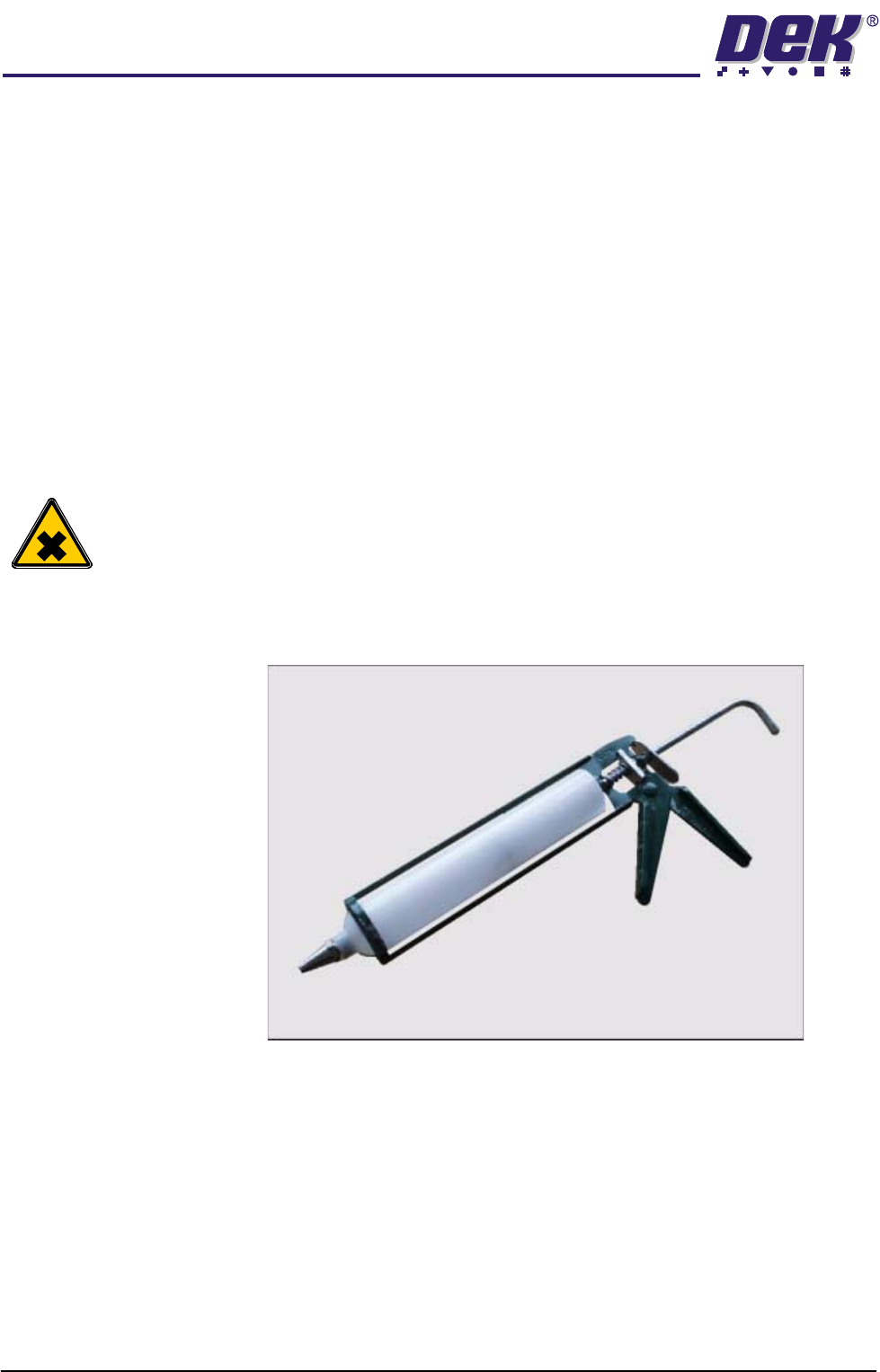
Manual Mastic Gun The standard cartridge, as listed above, can be fitted to a general purpose
mastic gun as shown in the Mastic Gun and Cartridge figure.
Figure 1-14 Mastic Gun and Cartridge
NOTE
For detailed procedures of print material filling refer to the Consumable Replen-
ishments chapter of the machine manual or the ProFlow Best Working Practices
guide (DEK Part No. 171280).
TECHNICAL REFERENCE
MECHANICAL DETAIL
Chapter Issue 8 Dec 02 ProFlow Manual 1.21
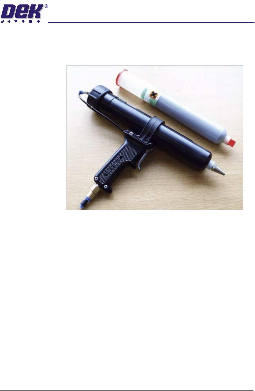
Pneumatic Gun The pneumatic gun is an optional accessory for the rechargeable transfer head.
The gun, supplied with a holster, is fitted to the machine and is pneumatically
connected to the factory air supply. The gun enables ready access and use for
regular charging of the ProFlow unit.
Figure 1-15 Pneumatic Gun (optional)
NOTE
For detailed procedures of print material filling refer to the Consumable Replen-
ishments chapter of the machine manual or the ProFlow Best Working Practices
guide (DEK Part No. 171280).
TECHNICAL REFERENCE
MECHANICAL DETAIL
1.22 ProFlow Manual Chapter Issue 8 Dec 02
Downstop The downstop applies to GSX, Lt and Infinity machines only. The purpose of
the downstop is to provide ProFlow with a zero pressure datum when ProFlow
is at contact height with the screen.
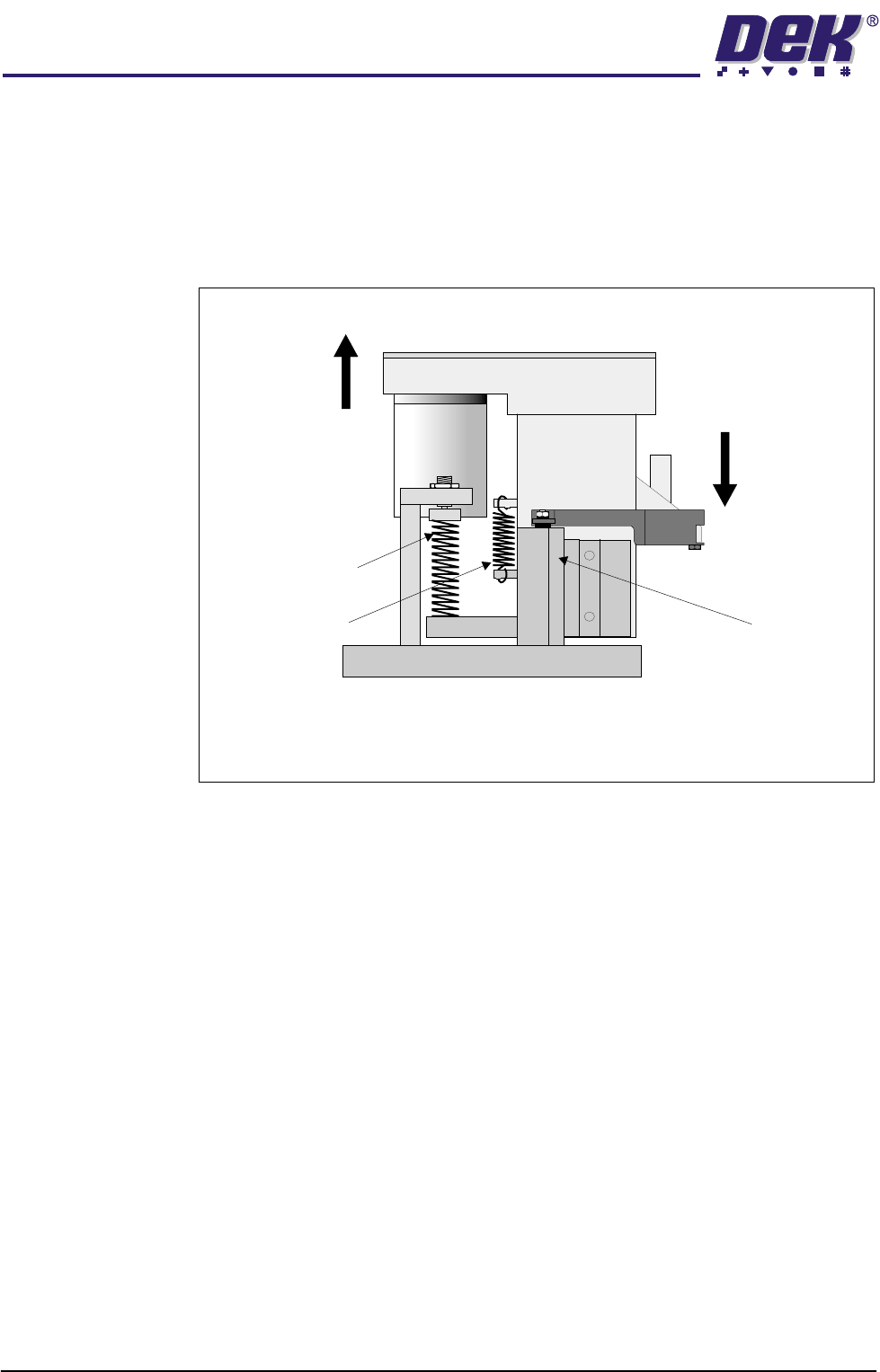
Downstop Position This is the position where the downstop is pre-tensioning the squeegee suspen-
sion and compression springs. A software offset can be implemented to +/-
10mm from the squeegee reference position.
Figure 1-16 Downstop Shown in Downstop Position
As the squeegee mechanism is mounted on a both positive and negative sprung
suspension system, any force exerted by the squeegee motor (relative to a fixed
position, ie the stencil), creates a damping force, causing the squeegee mount-
ing to move as it exceeds the sprung force.
The ProFlow downstop is fitted to the front squeegee mounting and drives
against the print carriage, compressing the main spring. This causes the
squeegee mechanism to be lifted relative to the print carriage, pre-loading the
system’s main compression spring and effecting a ‘solid’ platform for the
ProFlow to work from.
Side View of Squeegee Mounting Assembly
Front Squeegee Mount
Lowered Downstop in
Contact with Print
Carriage
Squeegee Mechanism
Pre-tensioned to Full
Extent
Print Carriage
Compression Spring
Suspension Spring