265ProFlow.pdf - 第44页
TECHNIC AL RE FERENCE ADJUS TMENT S AND SETTINGS 1.40 ProFlow Manual Chapter Issue 8 Dec 02 Figure 1-28 Cassette Low Sensor Adjustment Sof tware Pressur e Adjustment The sof tw are cont rolled regulator c an be instr uct…
TECHNICAL REFERENCE
ADJUSTMENTS AND SETTINGS
Chapter Issue 8 Dec 02 ProFlow Manual 1.39
ADJUSTMENTS AND SETTINGS
Cassette Low
Sensor
The cassette low sensor position can be changed in order to minimize print
material wastage. A graduated scale (millimetre) on the actuator cylinder body
provides a reference point for accurate sensor positioning, (Cassette Low
Sensor Adjustment figure refers). The sensor is moved up or down by loosen-
ing the securing screw, (1.5mm Allen key).
The factory setting for the sensor is set to 20mm on the graduated scale. Each
millimetre movement is equivalent to approximately 43gms of print material
usage.
WARNING
SOLDER PASTE AND SOLVENTS. WHEN USING OR HANDLING ANY SOLDER
PASTE OR SOLVENT FORMULATION THE MANUFACTURERS’ RECOMMEND
SAFETY PRECAUTIONS MUST BE STRICTLY ADHERED TO.
WARNING
PROTECTIVE CLOTHING. APPROVED PROTECTIVE CLOTHING SHOULD BE
WORN BY SOLDER PASTE AND SOLVENT HANDLERS AT ALL TIMES TO
ELIMINATE FUME INHALATION, EYE CONTACT, SKIN CONTACT AND
INGESTION.
The following procedure should be carried out when print material wastage is
excessive.
1. Gain access to the ProFlow unit by opening the machine cover.
2. Lift off the ProFlow pressure mechanism cover.
Cassette Option 3. Noting the present position of the sensor against the graduated marker,
loosen the sensor using a 1.5mm Allen key.
4. With each graduation on the graduation scale being equivalent to approxi-
mately 43gms of print material, move the sensor down by single graduations
until the optimum print material usage position is obtained, (Cassette Low
Sensor Adjustment figure refers).
5. Carefully re-tighten the sensor securing screw.
NOTE
To prevent damage to the sensor, do not overtighten grub screw.
6. Replace the pressure mechanism cover.
7. Close the machine cover.
Rechargeable
Transfer Head
Option
8. When using a rechargeable transfer head and paste low sensor activation
is required at the mid diaphragm point the reed sensor can be inverted so
that a higher sensor initiation can be achieved. (In this position the sensor
cable is at the bottom of the sensor.)
TECHNICAL REFERENCE
ADJUSTMENTS AND SETTINGS
1.40 ProFlow Manual Chapter Issue 8 Dec 02
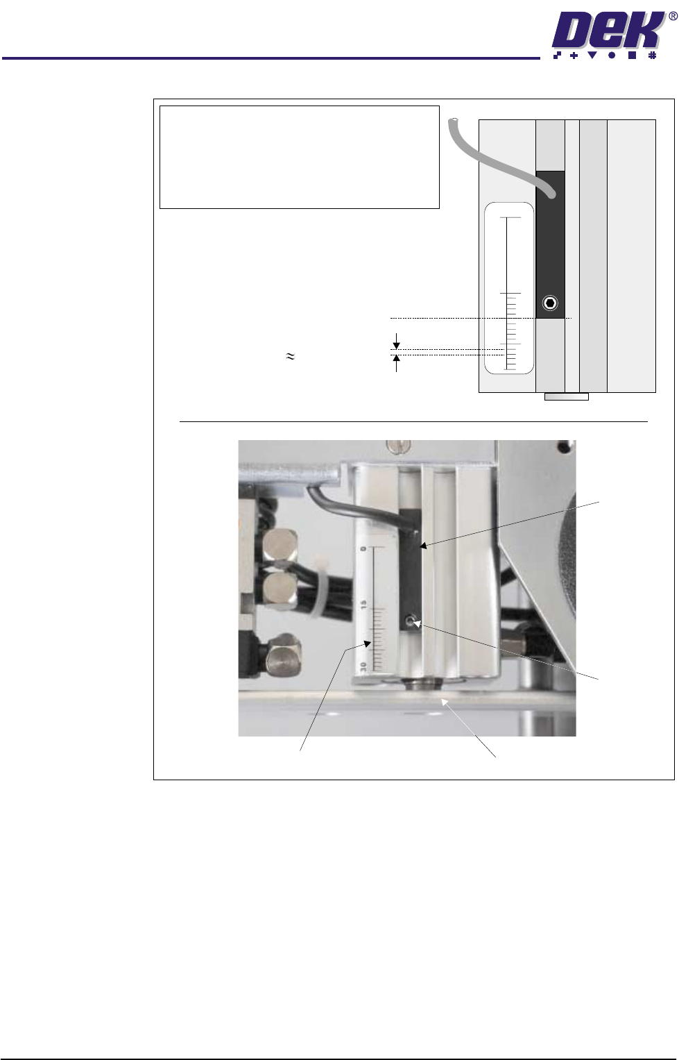
Figure 1-28 Cassette Low Sensor Adjustment
Software Pressure
Adjustment
The software controlled regulator can be instructed to supply and maintain
pneumatic pressure to the piston crosshead within the range of 0.0 bar to 4 bar,
or no pressure at all.
Software controlled piston pressure has four settings:
• Print Paste Pressure
• Knead Paste Pressure
• Idle Paste Pressure
• No Pressure
NOTE
For ProFlow cassette option - ensure that the
cable of the sensor is configured to the top.
Rechargeable transfer head option - sensor may
be inverted (cable to the bottom) if paste low
activation is required at mid way point.
Securing
Screw
Graduated Scale (1mm increments)
Piston Crosshead
Sensor
20 (mm) Factory Setting
1mm Graduation 43gms Print
Material Usage
30
15
0

TECHNICAL REFERENCE
ADJUSTMENTS AND SETTINGS
Chapter Issue 8 Dec 02 ProFlow Manual 1.41
NOTE
If Advanced ProFlow is set to enabled, Print Paste Pressure is replaced by the
following parameters, which can be independently set:
• FWD Start Pressure
• FWD End Pressure
• RWD Start Pressure
• RWD End Pressure
Print Paste Pressure This is the set operating pressure whilst the ProFlow unit is in the printing mode.
On removal of the print paste pressure (piston pressure), ie on completion of
print stroke, the print paste pressure is reduced to idle paste pressure.
NOTE
Print paste pressure can be adjusted in the product file under edit data or by
selecting the Adjust button during machine running.
Knead Paste
Pressure
This is the set operating pressure whilst the ProFlow unit is in the kneading
mode. On removal of the knead paste pressure (piston pressure), ie on
completion of kneading, the knead paste pressure is reduced to idle paste
pressure.
NOTE
Knead paste pressure can be adjusted in the product file under edit data or by
selecting the Adjust button during machine running.
Idle Paste Pressure A light pressure is applied whilst the ProFlow unit is idle but remaining in contact
with the stencil surface. This pressure is sufficient to prevent air pockets
forming in the ProFlow system but not enough to cause print material seepage.
NOTE
Idle paste pressure does not affect movement of the screen chase.
Idle paste pressure can be adjusted in the product file under edit data or by
selecting the Adjust button during machine running.
No Pressure No pressure is exerted whilst the printer is in the following configurations:
• When refilling or changing a cassette.
• Whilst the ProFlow unit is off the stencil.
• Whilst the ProFlow unit is being placed on, or lifted off the screen.
In the event of an E Stop action, pressure on the transfer head is released
altogether.
Upon restoration of system power any pressure that was previously applied to
the unit is restored, provided that the system is not re-initialized.