265ProFlow.pdf - 第30页
TECHNIC AL RE FERENCE ELECTRIC AL DETAIL 1.26 ProFlow Manual Chapter Issue 8 Dec 02 Jumper Link Fu nctions T est Point s Link S t atus Function Result LK1 Omitted Pseu do Dif feren tial G round Co nnect ion PCADAD IOCD, …
TECHNICAL REFERENCE
ELECTRICAL DETAIL
Chapter Issue 8 Dec 02 ProFlow Manual 1.25
ELECTRICAL DETAIL
For electrical detail on Infinity, Horizon and ELA machines refer to the
respective Technical Reference manual. For GSX and Lt machines only, a
PCADADIO card is used. The PCADADIO card is a multi-purpose I/O board
with the following functions:
• 8 Differential Multiplexed Analogue Inputs.
• Two Analogue Outputs.
• 16 Digital I/Os.
• 3 Counter-timer Channels.
The operation of these functions are controlled using the PC XT bus and link
options.
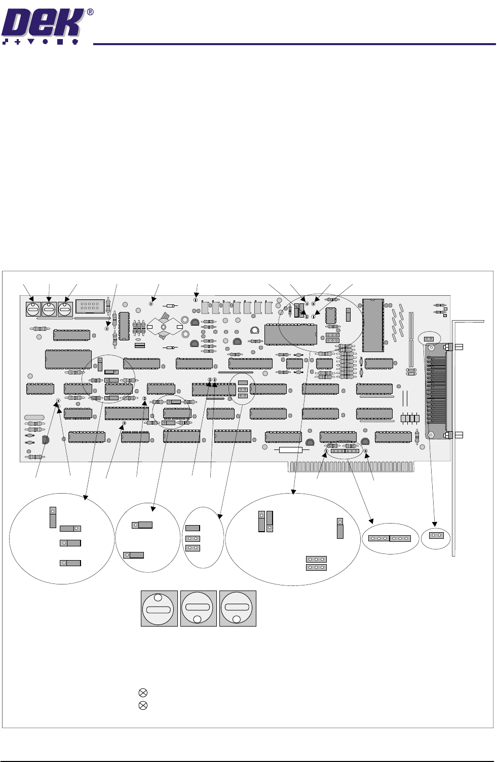
Figure 1-19 PCADADIO Card Layout
1 1 1
TP13 TP10 TP9 TP2 TP3TP5TP6
TP1TP4TP12
TP7TP8
TP14 TP15
TP11
SW1 SW2 SW3
1
8 8
PCADADIO, ENCLOSURE Y3, CARD X3
RED
GREEN
Illuminates when board is accessed by processor.
Illuminates when board is in normal use.
Sets a unique board-slot address for PCIB40 #5 .
(I/0 addressing uses this base address to point to data channels).
SWITCH SW1 SW2 SW3
8
1
8
THIS BOARD SLOT POSITION =
SW
1
SW
2
SW
3
LK14
B
B
A
A
BA
LK15
B
A
LK16
LK17
LK13
A
B
LK12
A
B
LK9
LK10
LK11
LK6
LK5
LK3
LK7
LK8
A
A
A
A
A
B
B
B
B
B
LK1
LK2LK4
BAA
B
TECHNICAL REFERENCE
ELECTRICAL DETAIL
1.26 ProFlow Manual Chapter Issue 8 Dec 02
Jumper Link Functions
Test Points
Link Status Function Result
LK1 Omitted Pseudo Differential Ground Connection PCADADIOCD, different inputs
LK2 Omitted ADC Interrupt Selection Not Used
LK3 A Differential/Single-ended Input Selection PCADADIOCD
LK4 Omitted Counter/Timer Interrupt Selection Not Used
LK5 Omitted DAC1 Output Range 0V to 10V
LK6 Omitted DAC0 Output Range 0V to 10V
LK7 B ADC Input Range -10V - to +10V
LK8 A ADC Input Range -10V - to +10V
LK9 Fitted ADC Trigger Source Enable software triggering
LK10 Omitted ADC Trigger Source Disable hardware triggering
LK11 Omitted ADC Trigger Source Disable Counter/timer channel A triggering
LK12 B Digital I/O Reset State Digital I/O lines DIG0-3
LK13 B Digital I/O Reset State Digital I/O lines DIG4-75
LK14 B Digital I/O Reset State Digital I/O lines DIG8-11
LK15 B Digital I/O Reset State Digital I/O lines DIG12-15
LK16 B Counter/Timer Channel A Clock Sequence 1Mhz Clock
LK17 A Digital I/O Reset Test Link Automated board testing of the I/O’s
Test Point Function
TP1 PCbus IRQ2
TP2 DAC Voltage Reference
TP3 +5V Analogue
TP4 PCbus IRQ3
TP5 Analogue + Supply (Approx. 15V)
TP6 Analogue - Supply (Approx. - 15V)
TP7 ADC Chip Enable
TP8 ADC Status Line
TP9 Analogue Ground
TP10 Digital Ground
TP11 Buffered Reset Active Low
TP12 I/O Address Match
TP13 +5V Digital
TP14 Device Write Active Low
TP15 Device Read Active Low
TECHNICAL REFERENCE
DRIVES AND SENSORS
Chapter Issue 8 Dec 02 ProFlow Manual 1.27
DRIVES AND SENSORS
Motors (GSX, Lt and Infinity)
The ProFlow system on GSX, Lt and Infinity machines utilizes the machines
existing squeegee motors and sensors for all vertical movement configurations.
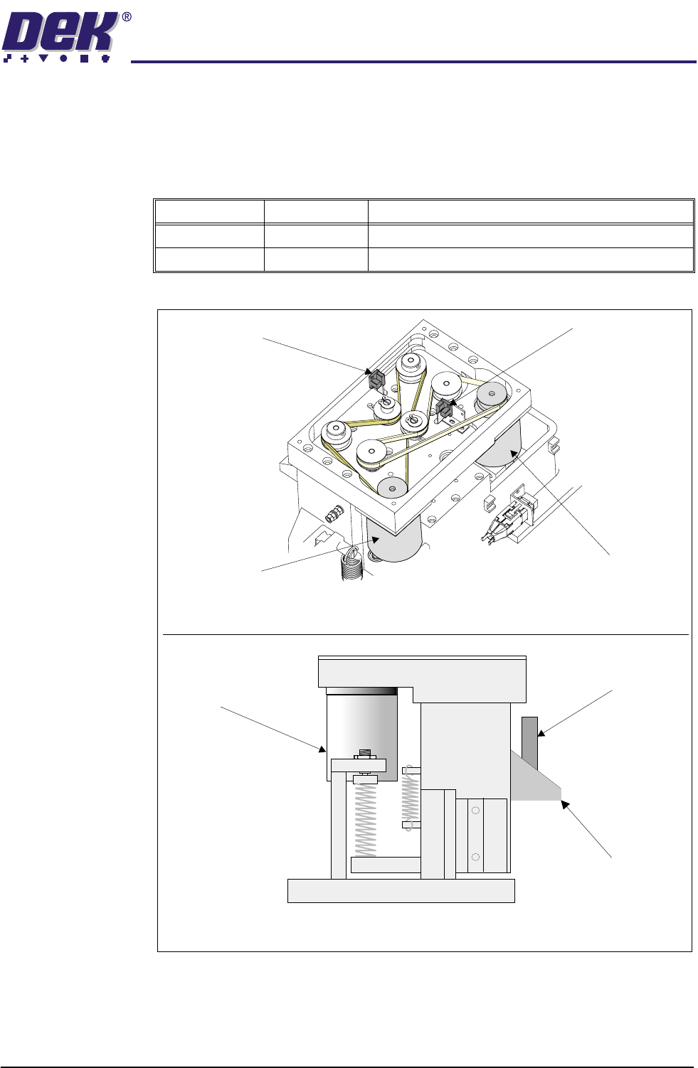
Figure 1-20 Squeegee Motor and Sensor Locations
Name Type Functional Description
Front Squeegee Stepper Motor Raises and lowers the downstop to the required height
Rear Squeegee Stepper Motor Raises and lowers the ProFlow to the required height
Side View on Squeegee Mounting Assembly
Stepper Motor
Drive (2 positions)
Rear Squeegee
Attachment Plate
Front Squeegee
Attachment Plate
Front Squeegee
Home Sensor
Front Squeegee
Stepper Motor
Rear Squeegee
Stepper Motor
Rear Squeegee
Home Sensor
Rear View of Printhead Pressure Mechanism (cover removed)