265ProFlow.pdf - 第47页
TECHNI CAL REFEREN CE REPLACEM ENT PROC EDURES Chapter Issue 8 Dec 02 ProFlow Manual 1.43 REPLACEMENT PROCEDURES Squeegees to Pr oFlow (GSX and Lt) Inst ances may o ccur when the m achine is r equired to print u sing the…
TECHNICAL REFERENCE
ADJUSTMENTS AND SETTINGS
1.42 ProFlow Manual Chapter Issue 8 Dec 02
ProFlow Stencil
Support
The ProFlow stencil support option provides stencil support when printing
boards that are narrower than the ProFlow transfer head thus avoiding potential
paste smearing onto the top of the stencil.
The standard height when the adjustable tooling top is in the closed position is
81mm. The support comprises the following items:
• Changeable Gauge Plate
• Tooling Bottom
• Adjustable Tooling Top
NOTE
Refer to Board Support Tooling chapter of the machine Technical Reference
manual for further information.
Height Adjustment To set the ProFlow stencil support to the correct height carry out the following:
1. Loosen the 7mm hexagonal nut securing the tooling top and tooling bottom.
2. Slide the adjustable tooling top upwards to open up the tooling top and
bottom faces.
3. Position two printed circuit boards to be printed between the tooling top and
bottom opening faces, (Setting Up Stencil Support Height figure refers).
4. Tighten the bolt locking the adjustable tooling top to the tooling bottom.
5. Remove both printed circuit boards.
The support is now set to the correct screen height, ie 81mm + thickness of
board.
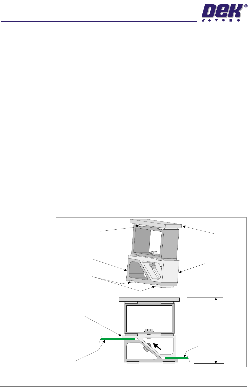
Figure 1-29 Setting Up Stencil Support Height
Changeable
Gauge Plate
Tooling Bottom
Magnetic Feet
Magnetic Support
(2 positions)
Adjustable Tooling
Top
Board
Adjustable
Tooling Top
Board
Stencil Support
Height (81mm +
PCB Thickness)
TECHNICAL REFERENCE
REPLACEMENT PROCEDURES
Chapter Issue 8 Dec 02 ProFlow Manual 1.43
REPLACEMENT PROCEDURES
Squeegees to ProFlow (GSX and Lt)
Instances may occur when the machine is required to print using the ProFlow
module configuration. The following procedure details how to revert the
machine from squeegee use to the ProFlow configuration:
1. In Diagnostics ensure that the squeegees are homed. Position the print
carriage so that removal and fit is carried out within easy reach.
2. Switch the machine OFF and disconnect pneumatics.
3. If squeegees are fitted, remove to a safe stowage.
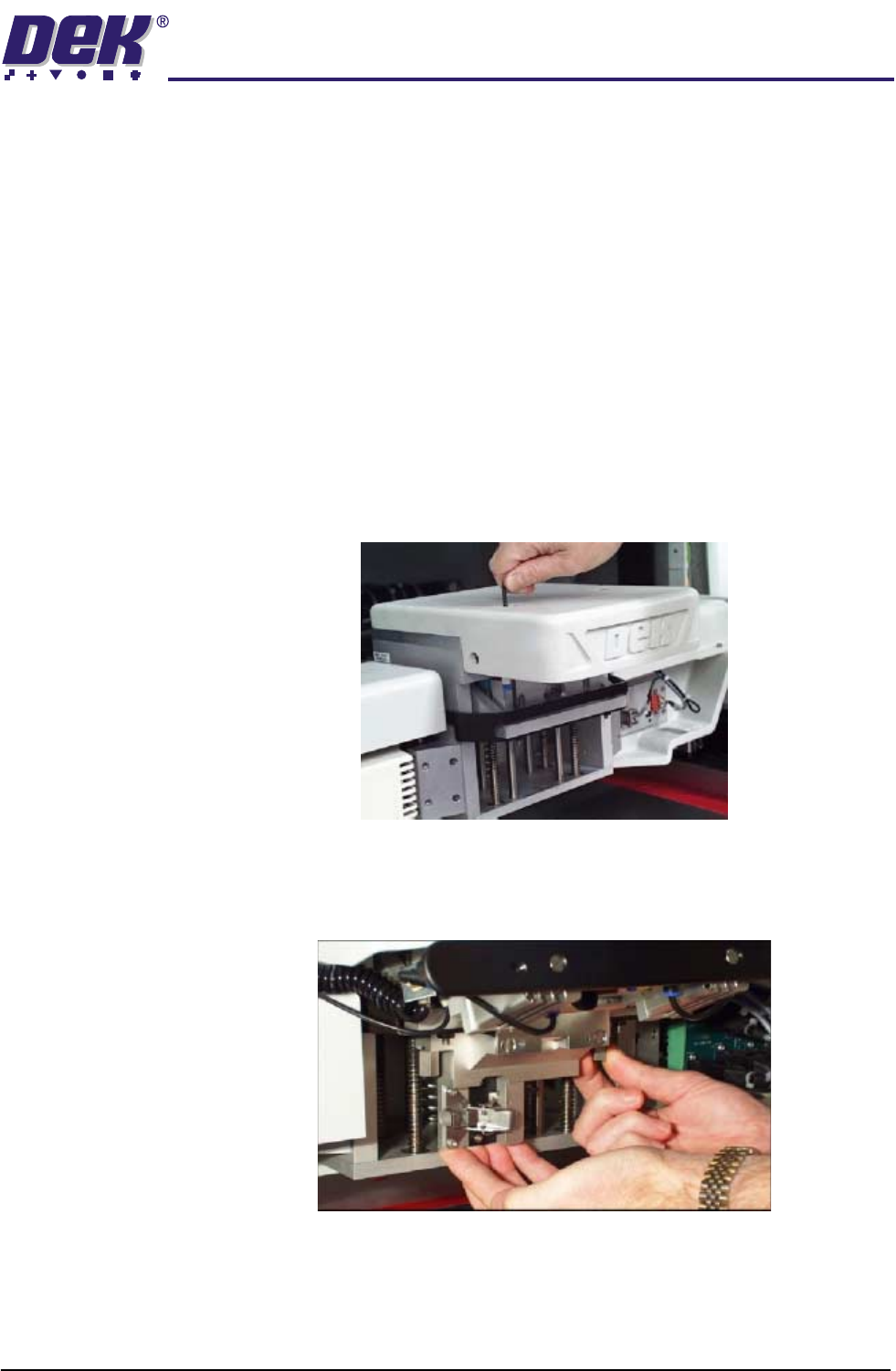
4. Using an extended 4mm Allen key (Pt. No. 137814), remove the front and
rear squeegee 'I' bars (access to the screws for the front 'I' bar is possible
through the hole in the top of the light shroud - figure below refers).
5. Using the existing screws, fit and secure the ProFlow downstop to the front
squeegee 'I' bar mounting position. Ensure that the downstop arms fit
above, to rest upon, the printhead linear webs.
6. Fit the pressure mechanism part of the ProFlow unit to the rear squeegee
mounting plate (where the 'I' bar normally fits) by means of the two securing
bolts. These bolts are easier accessed by fitting the unit in the unlatched
position. Tighten using a 5mm Allen key.
TECHNICAL REFERENCE
REPLACEMENT PROCEDURES
1.44 ProFlow Manual Chapter Issue 8 Dec 02
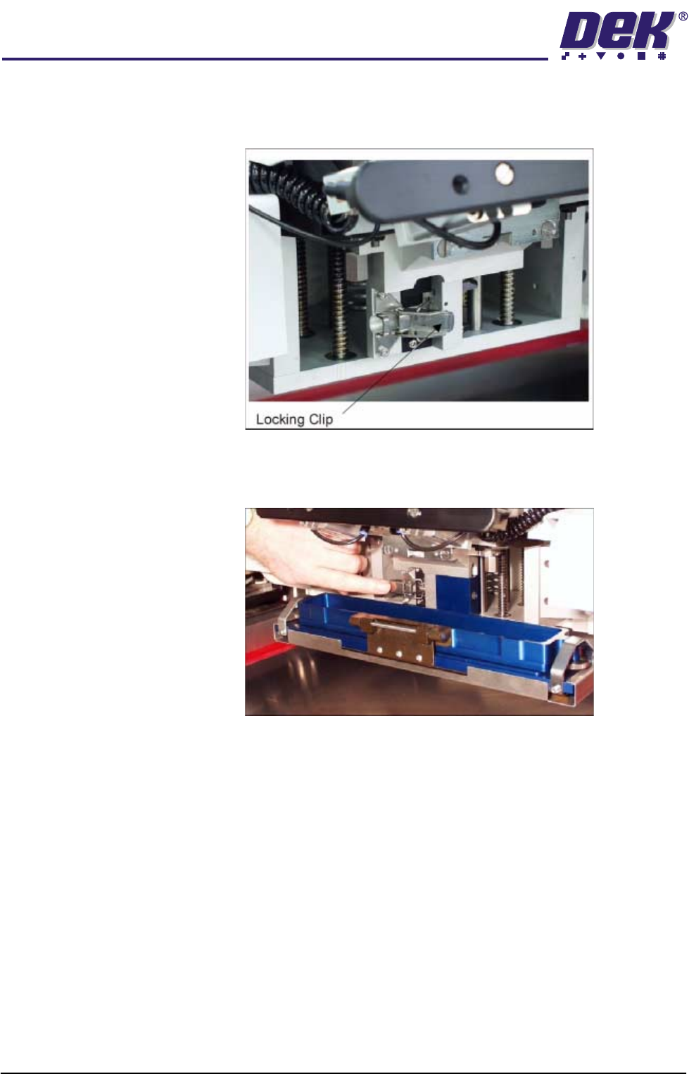
7. Ensure that the locking clip on the pressure mechanism is pressed over to
the right and clicks into place, as shown in the figure below. This ensures
that the locking clip is in the correct position to secure the transfer head.
8. Locate and fit the ProFlow transfer head unit to the pressure mechanism by
means of the two locating dowels. Slide the unit onto the pressure mecha-
nism. Once the unit is slid fully home, it is secured by closing the locking clip.
9. Plug the electrical connection from the ProFlow unit into the left hand side
of the light shroud.
CAUTION
ELECTRICAL CONNECTION.
The electrical connection informs the
machine of ProFlow fitment and must always be connected whilst the
ProFlow unit is fitted otherwise damage can occur if machine is run.
10. Locate the two pneumatic connectors on the underside of the light shroud
and connect the curly pneumatic leads from the pressure mechanism to the
respective left and right connector.
11. Connect the pneumatics and switch the machine to ON. To ensure the
machine recognizes the ProFlow module the following indications on the
machine MMI are evident:
a. During the boot up sequence the operator is prompted to fit the ‘ProFlow
cover’.
b. The soft key that previously indicated 'Paste Load' now indicates 'Knead
Paste'.