265ProFlow.pdf - 第28页
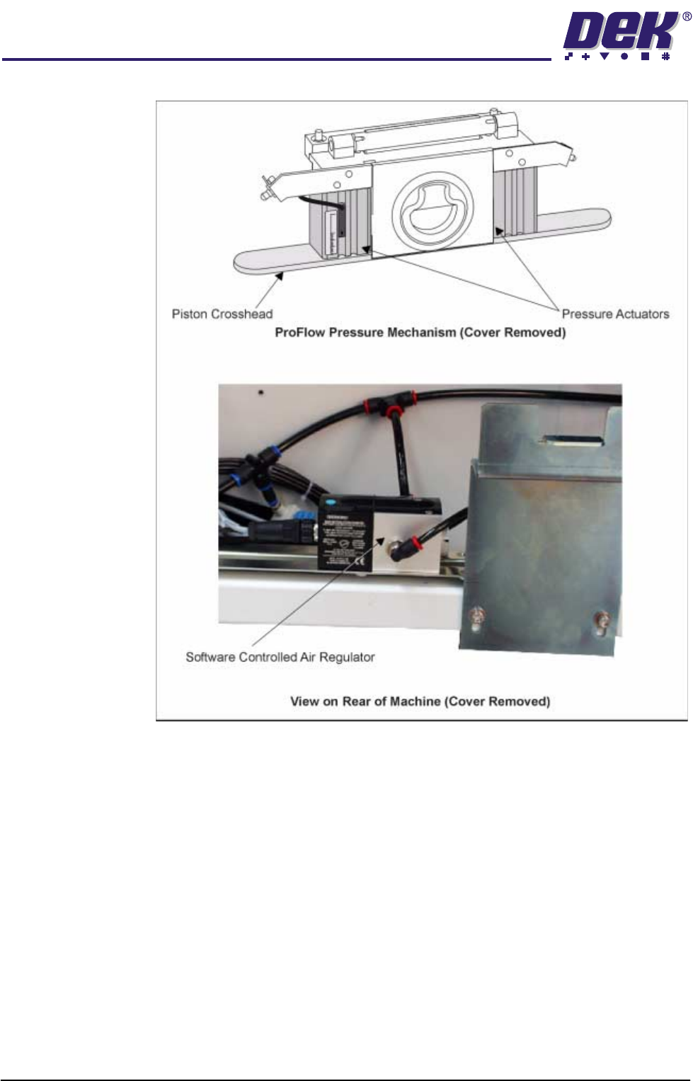
TECHNIC AL RE FERENCE MECHANICAL DETAIL 1.24 ProFlow Manual Chapter Issue 8 Dec 02 Figure 1-18 Sof tware Controlled Pr essure Mechani sm - Norgren
TECHNICAL REFERENCE
MECHANICAL DETAIL
Chapter Issue 8 Dec 02 ProFlow Manual 1.23
Pneumatic Supply The pneumatic air supply offers a positive force to the ProFlow system during
the print cycle providing a continuous supply of print material to the stencil.
NOTE
This force should not be confused with system pressure which is the force
applied to the ProFlow unit by the printhead mechanism stepper motor.
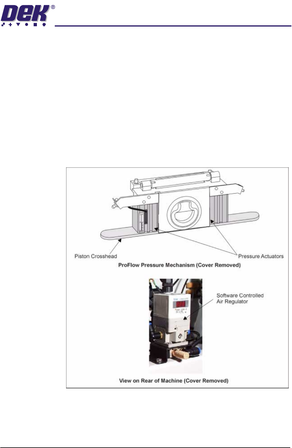
Software Control System air pressure is applied to the piston crosshead enabling the pressure
actuators. ProFlow pressure is factory set at 2.0 bar, however this can be
adjusted under edit data.
The Idle Paste Pressure parameter applies a light pressure onto the piston
crosshead and print material system whilst the ProFlow unit is idle, but remain-
ing on the stencil surface. (Refer to Adjustments and Settings - Software
Pressure Adjustment Section of this chapter for further details.)
An SMC SCAR is used on GSX and Lt machines and a Norgren SCAR on all
other machines.
Figure 1-17 Software Controlled Pressure Mechanism - SMC
TECHNICAL REFERENCE
MECHANICAL DETAIL
1.24 ProFlow Manual Chapter Issue 8 Dec 02
Figure 1-18 Software Controlled Pressure Mechanism - Norgren
TECHNICAL REFERENCE
ELECTRICAL DETAIL
Chapter Issue 8 Dec 02 ProFlow Manual 1.25
ELECTRICAL DETAIL
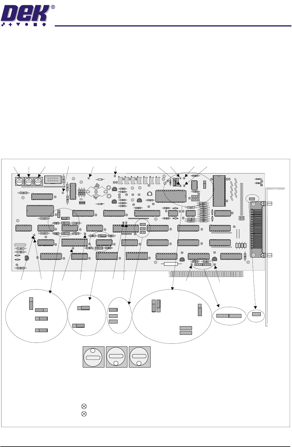
For electrical detail on Infinity, Horizon and ELA machines refer to the
respective Technical Reference manual. For GSX and Lt machines only, a
PCADADIO card is used. The PCADADIO card is a multi-purpose I/O board
with the following functions:
• 8 Differential Multiplexed Analogue Inputs.
• Two Analogue Outputs.
• 16 Digital I/Os.
• 3 Counter-timer Channels.
The operation of these functions are controlled using the PC XT bus and link
options.
Figure 1-19 PCADADIO Card Layout
1 1 1
TP13 TP10 TP9 TP2 TP3TP5TP6
TP1TP4TP12
TP7TP8
TP14 TP15
TP11
SW1 SW2 SW3
1
8 8
PCADADIO, ENCLOSURE Y3, CARD X3
RED
GREEN
Illuminates when board is accessed by processor.
Illuminates when board is in normal use.
Sets a unique board-slot address for PCIB40 #5 .
(I/0 addressing uses this base address to point to data channels).
SWITCH SW1 SW2 SW3
8
1
8
THIS BOARD SLOT POSITION =
SW
1
SW
2
SW
3
LK14
B
B
A
A
BA
LK15
B
A
LK16
LK17
LK13
A
B
LK12
A
B
LK9
LK10
LK11
LK6
LK5
LK3
LK7
LK8
A
A
A
A
A
B
B
B
B
B
LK1
LK2LK4
BAA
B