265ProFlow.pdf - 第46页
TECHNIC AL RE FERENCE ADJUS TMENT S AND SETTINGS 1.42 ProFlow Manual Chapter Issue 8 Dec 02 ProFlow St encil Support The ProFlow ste ncil sup port option pr ovides stenc il support when print ing boards that are narrower…

TECHNICAL REFERENCE
ADJUSTMENTS AND SETTINGS
Chapter Issue 8 Dec 02 ProFlow Manual 1.41
NOTE
If Advanced ProFlow is set to enabled, Print Paste Pressure is replaced by the
following parameters, which can be independently set:
• FWD Start Pressure
• FWD End Pressure
• RWD Start Pressure
• RWD End Pressure
Print Paste Pressure This is the set operating pressure whilst the ProFlow unit is in the printing mode.
On removal of the print paste pressure (piston pressure), ie on completion of
print stroke, the print paste pressure is reduced to idle paste pressure.
NOTE
Print paste pressure can be adjusted in the product file under edit data or by
selecting the Adjust button during machine running.
Knead Paste
Pressure
This is the set operating pressure whilst the ProFlow unit is in the kneading
mode. On removal of the knead paste pressure (piston pressure), ie on
completion of kneading, the knead paste pressure is reduced to idle paste
pressure.
NOTE
Knead paste pressure can be adjusted in the product file under edit data or by
selecting the Adjust button during machine running.
Idle Paste Pressure A light pressure is applied whilst the ProFlow unit is idle but remaining in contact
with the stencil surface. This pressure is sufficient to prevent air pockets
forming in the ProFlow system but not enough to cause print material seepage.
NOTE
Idle paste pressure does not affect movement of the screen chase.
Idle paste pressure can be adjusted in the product file under edit data or by
selecting the Adjust button during machine running.
No Pressure No pressure is exerted whilst the printer is in the following configurations:
• When refilling or changing a cassette.
• Whilst the ProFlow unit is off the stencil.
• Whilst the ProFlow unit is being placed on, or lifted off the screen.
In the event of an E Stop action, pressure on the transfer head is released
altogether.
Upon restoration of system power any pressure that was previously applied to
the unit is restored, provided that the system is not re-initialized.
TECHNICAL REFERENCE
ADJUSTMENTS AND SETTINGS
1.42 ProFlow Manual Chapter Issue 8 Dec 02
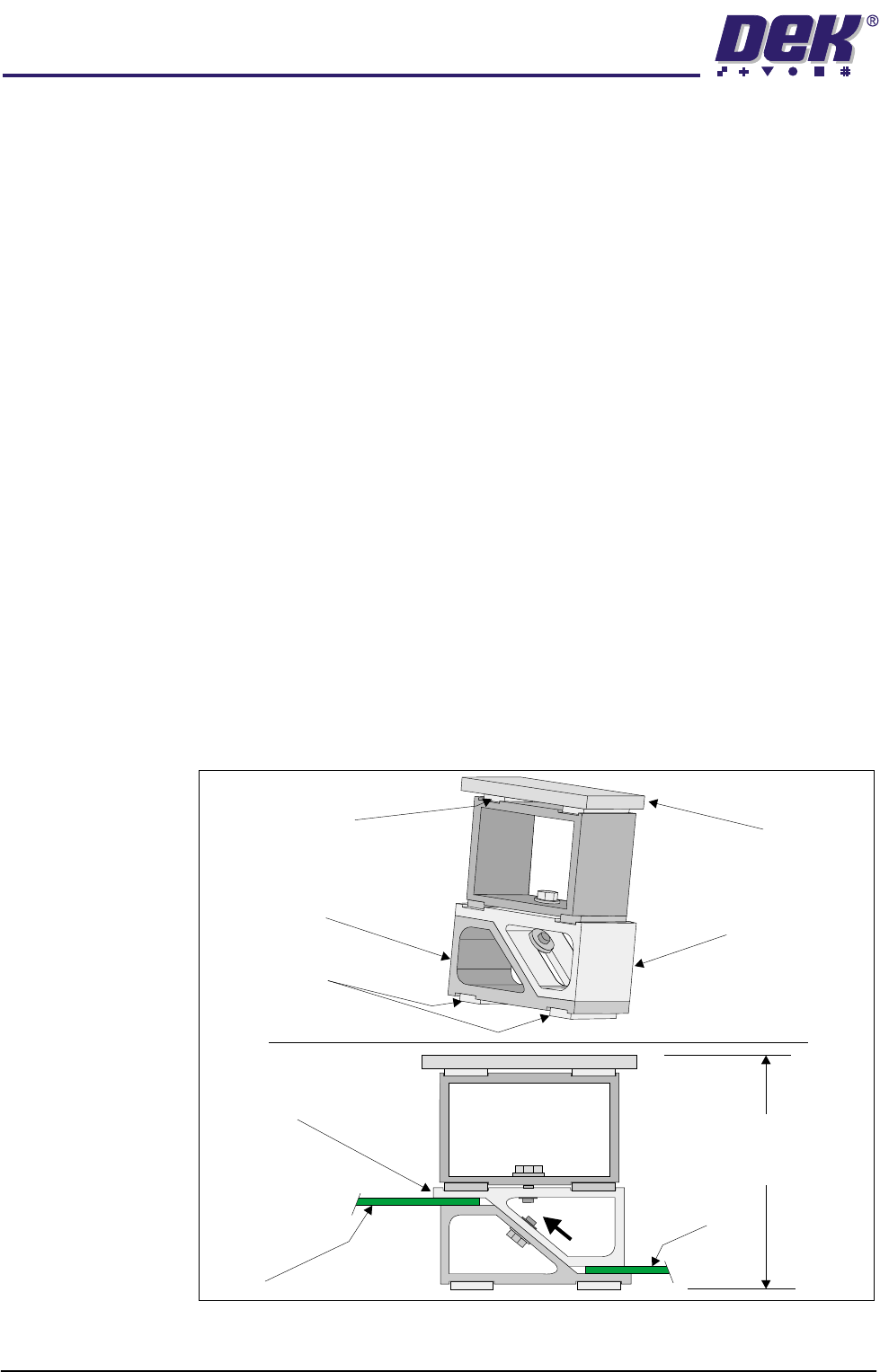
ProFlow Stencil
Support
The ProFlow stencil support option provides stencil support when printing
boards that are narrower than the ProFlow transfer head thus avoiding potential
paste smearing onto the top of the stencil.
The standard height when the adjustable tooling top is in the closed position is
81mm. The support comprises the following items:
• Changeable Gauge Plate
• Tooling Bottom
• Adjustable Tooling Top
NOTE
Refer to Board Support Tooling chapter of the machine Technical Reference
manual for further information.
Height Adjustment To set the ProFlow stencil support to the correct height carry out the following:
1. Loosen the 7mm hexagonal nut securing the tooling top and tooling bottom.
2. Slide the adjustable tooling top upwards to open up the tooling top and
bottom faces.
3. Position two printed circuit boards to be printed between the tooling top and
bottom opening faces, (Setting Up Stencil Support Height figure refers).
4. Tighten the bolt locking the adjustable tooling top to the tooling bottom.
5. Remove both printed circuit boards.
The support is now set to the correct screen height, ie 81mm + thickness of
board.
Figure 1-29 Setting Up Stencil Support Height
Changeable
Gauge Plate
Tooling Bottom
Magnetic Feet
Magnetic Support
(2 positions)
Adjustable Tooling
Top
Board
Adjustable
Tooling Top
Board
Stencil Support
Height (81mm +
PCB Thickness)
TECHNICAL REFERENCE
REPLACEMENT PROCEDURES
Chapter Issue 8 Dec 02 ProFlow Manual 1.43
REPLACEMENT PROCEDURES
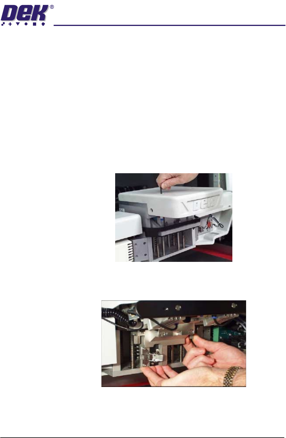
Squeegees to ProFlow (GSX and Lt)
Instances may occur when the machine is required to print using the ProFlow
module configuration. The following procedure details how to revert the
machine from squeegee use to the ProFlow configuration:
1. In Diagnostics ensure that the squeegees are homed. Position the print
carriage so that removal and fit is carried out within easy reach.
2. Switch the machine OFF and disconnect pneumatics.
3. If squeegees are fitted, remove to a safe stowage.
4. Using an extended 4mm Allen key (Pt. No. 137814), remove the front and
rear squeegee 'I' bars (access to the screws for the front 'I' bar is possible
through the hole in the top of the light shroud - figure below refers).
5. Using the existing screws, fit and secure the ProFlow downstop to the front
squeegee 'I' bar mounting position. Ensure that the downstop arms fit
above, to rest upon, the printhead linear webs.
6. Fit the pressure mechanism part of the ProFlow unit to the rear squeegee
mounting plate (where the 'I' bar normally fits) by means of the two securing
bolts. These bolts are easier accessed by fitting the unit in the unlatched
position. Tighten using a 5mm Allen key.