00195397-01_Installation Manual Setup Center 2.3.pdf - 第43页
Installation Optional: Docking Station Hardware Installation Installation Manual SIPLACE Setup Center 2.3 43 X Switch on the power supply. X You will find a control lamp on the front of the de vice. This will shine when …
Installation
Hardware Installation Optional: Docking Station
42 Installation Manual SIPLACE Setup Center 2.3
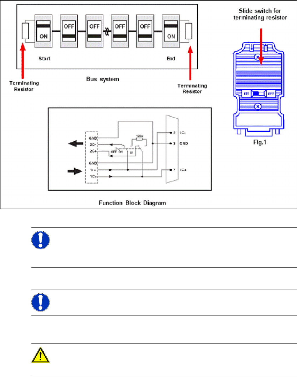
Connection Example 1 and 2
5-15: Connection example 1 and 2: CAN bus cable
Compressed Air and Power Supplies
X Connect to the compressed air supply.
X Set the pressure reducer on the pneumatic connection (external) to 5.5 bar.
X Switch off the power supply and connect the CAN Bus cable to the device.
NOTE:
The terminating resistors are activated via the slide switch (XXXXXX) at the starting and final
point of the bus system. At the same time the connection points (2C+ / 2C-) for the outgoing bus
cable are switched off.
At all other nodes of the bus system the corresponding terminating resistor must be activated!
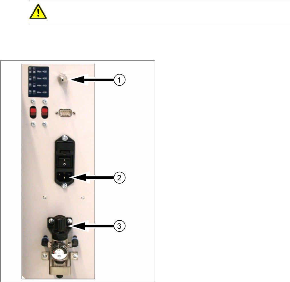
NOTE:
The compressed air and power connections can be found on the back of the docking station.
DANGER:
Never cover the air discharge opening in the integrated fan and the ventilation slits on the side
of the device!
Covering these could lead to overheating and destruction of the power pack.
Installation
Optional: Docking Station Hardware Installation
Installation Manual SIPLACE Setup Center 2.3
43
X Switch on the power supply.
X You will find a control lamp on the front of the device. This will shine when power is correctly supplied
to the device.
5.2.4.5 Firmware download for docking station
X Setup Center 2.3 can update the firmware of your docking station.
To learn how to update the firmware of your docking station, please refer to the chapter "Docking
Station Firmware Download" of the document User Guide Setup Center 2.3, item no. 00195402-xx.
DANGER:
Make sure that nobody is using the connected component trolley when you switch the power on.
5-16: Docking station: compressed air and power supplies
Legend:
1. Compressed Air Connection
2. Power Connection
3. Set Compressed Air
Installation
Software Installation Setup Center
44 Installation Manual SIPLACE Setup Center 2.3
5.3 Software Installation
5.3.1 Setup Center
The following steps have to be performed to install the required system components on the specific
computer:
1. General settings, steps that are identical for all setup types
2. Setup types, the following setup types can be selected:
– SIPLACE Setup Center GUI
– SIPLACE Setup Center Database
– SIPLACE Setup Center Complete
5.3.1.1 General Settings
These steps are identical for all setup types. The subsequent steps only differ once you have selected
the setup type you require.
Run through the following steps to start the installation and then refer to the relevant section for your
specific setup type.
Step 1
X Insert the SIPLACE Setup Center installation CD into the CD-ROM drive. The installation routine
starts automatically.
X You can also start the installation by running the
Setup.exe
program located in the root directory on
the installation CD.
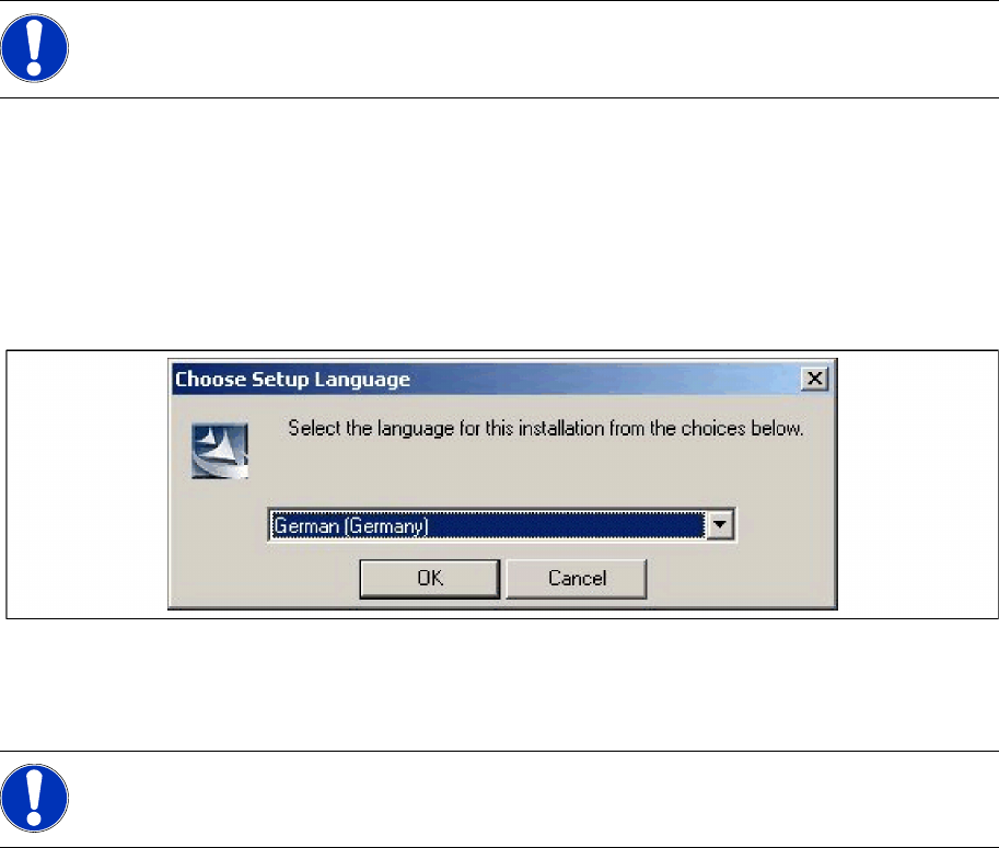
X This starts the user-controlled installation of SIPLACE Setup Center; you are prompted to select the
installation language.
5-17: "Choose setup language" dialog box
X Select the language you want.
X Click OK.
NOTE:
You require administrator rights for the installation procedure!
NOTE:
This decision only relates to the language used during the installation routine!