CX200-4(Maint).pdf - 第25页
Fig. 4A14-1 Front View of Machine Component Receiving Box 1D8 Daily Cleaning Clean with a vacuum cleaner . 1.3 Maintenance Spots 01 10-003 1-14 AFO01ETRP
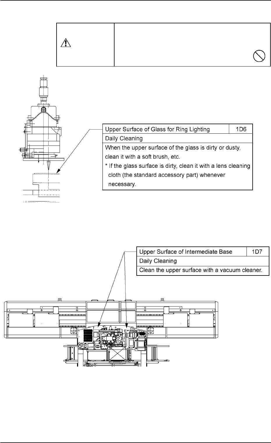
(4) Component Recognition Section
(5) Main Section of Machine Intermediate Base/Component Receiving Box
Fig. 4A14
1.3 Maintenance Spots
0110-003 1-13 AFO01ETRP
Use a suction force (a vacuum cleaner) for cleaning.
Do not blow air with an air gun.
If the component recognition section is dirty or
dusty, incorrect recognition will result.
CAUTION
Fig. 4A13
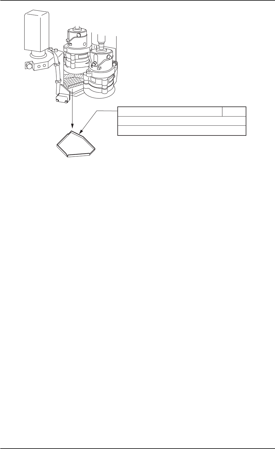
Fig. 4A14-1 Front View of Machine
Component Receiving Box 1D8
Daily Cleaning
Clean with a vacuum cleaner.
1.3 Maintenance Spots
01 10-003 1-14 AFO01ETRP
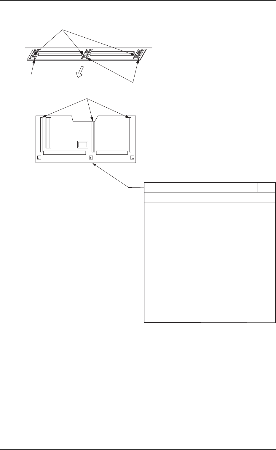
(6) Cutter Section Component Drop Prevention Cover
1.3 Maintenance Spots
0110-003 1-15 AFO01ETRP
Component Drop Prevention Cover 1D9
Daily Cleaning
When components are scattered over the
cover, follow the steps below to remove them.
1. Set the timing angle of the rotary turret to
approx. 200 degrees and turn off the power
supply before cleaning work.
2. Remove the three screws and pull out the
cover toward the rear side of the machine.
3. Clean the cover with a vacuum cleaner, etc.
4. Attach the cover to the machine such that
the rail section of the cover is correctly
inserted into the guide section of the machine.
5. Attach the three screws.
Pull out.
Guide Section
Guide Section
Screws
Rail Section
Fig. 4A15 Rear View of Machine