CX200-4(Maint).pdf - 第61页
(1-4) Press the [Cam Lock] switch on the head. Fig. 4A64-1 (1-5) Select one (Nozzle # of the nozzle to be detached) of the but- tons in “*7” and press the [ON] button (entitled “MOVE”). In two seconds, press the [ENABLE]…
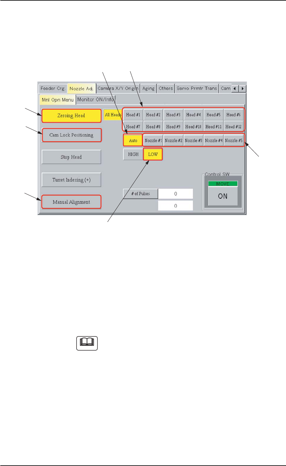
(1-2) Move the head (having the nozzle to be detached) to the place-
ment station with the [Manual Alignment] button in the “Mnl Opn
Menu” tab sheet. (Operation Sequence: “UNIT ADJ.” Window
(Submenu) Æ “Nozzle Adj.” Tab Æ “Mnl Opn Menu” Tab Æ
[Manual Alignment] Button)
Fig. 4A64 “Mnl Opn Menu” Tab Sheet
(1-3) Select one of the buttons (Head Nos.) in “*2”, the [Auto] button
(*3), the [LOW] button (*4), and the [Cam Lock Positioning]
(*5).
Press the [ENABLE] button on the operation panel in two sec-
onds after the [ON] button (entitled “MOVE”).
The “LOW” nozzle on the specified head turns toward the front
side of the machine.
If the head does not turn, use the [Zeroing Head] button (*6) to
zero the specified head and perform the above operation
again.
1.4 Maintenance Method
0110-003 1-49 AFO01ETRP
Note
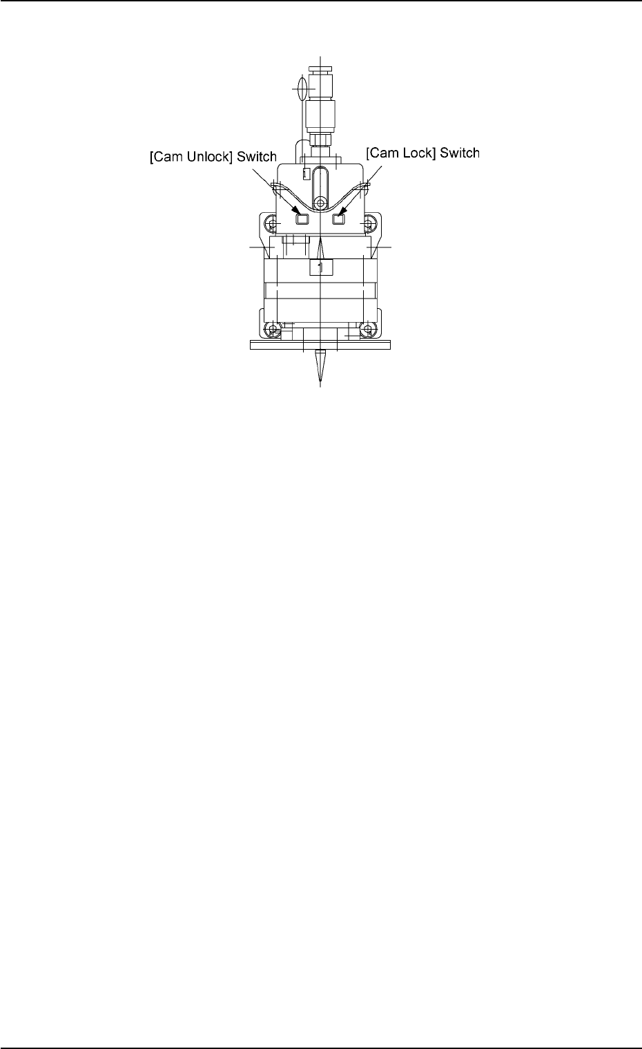
(1-4) Press the [Cam Lock] switch on the head.
Fig. 4A64-1
(1-5) Select one (Nozzle # of the nozzle to be detached) of the but-
tons in “*7” and press the [ON] button (entitled “MOVE”). In two
seconds, press the [ENABLE] button on the operation panel.
The selected vacuum nozzle will face toward the front side of
the machine. Press the [Cam Unlock] switch.
1.4 Maintenance Method
0110-003 1-50 AFO01ETRP
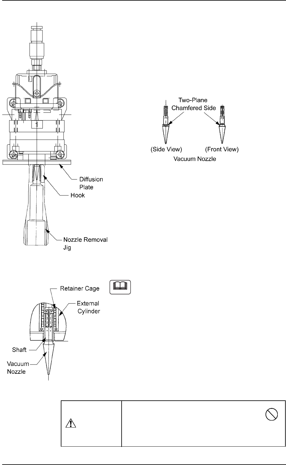
(1-6) Detachment of Vacuum Nozzle
Push the bottom of the nozzle removal jig gently and set it on the vacuum
nozzle such that the hook is engaged correctly with the two-plane cham-
fered side of the vacuum nozzle.
Note: The nozzle removal jig cannot be used for nozzle type 031 (φ6
nozzle). Detach the nozzle by hand.
Fig. 4A65
(1-7) Pull down the nozzle removal jig to detach the vacuum nozzle.
(a) Do not score the diffusion plate while detaching
a vacuum nozzle.
(b) A miniature stroke bearing is used at the
nozzle up/down movement section which
consists of the shaft, the retainer cage, and the
external cylinder units.
When the section is disassembled by mistake,
be sure to correctly reassemble each unit
which belongs to the section.
When the nozzle is detached, the miniature
stroke bearing and the shaft section should not
be removed.
Fig. 4A64-2
Note
Avoid getting the removed vacuum nozzle
magnetized.
When the nozzle is magnetized, an error will occur
in component pick-up or placement.
CAUTION
Fig. 4A66
1.4 Maintenance Method
0110-003 1-51 AFO01ETRP