CX200-4(Maint).pdf - 第70页
• Attachment of Miniature Stroke Bearing (1) Attachment of Seals and Collar to Outer Cylinder of Miniature Stroke Bearing (1-1) Wipe the seals with a dry cloth and apply “DAPHNE EPONEX GREASE No. 1” to the internal side …
• Lubrication of Miniature Stroke Bearing
(1) Apply 0.01 cc of “DAPHNE EPONEX
GREASE No. 1” to the internal cages of the
outer cylinder.
Note: Use a metallic stick such as a hexagon
wrench for the lubrication. Do not use a
cotton swab.
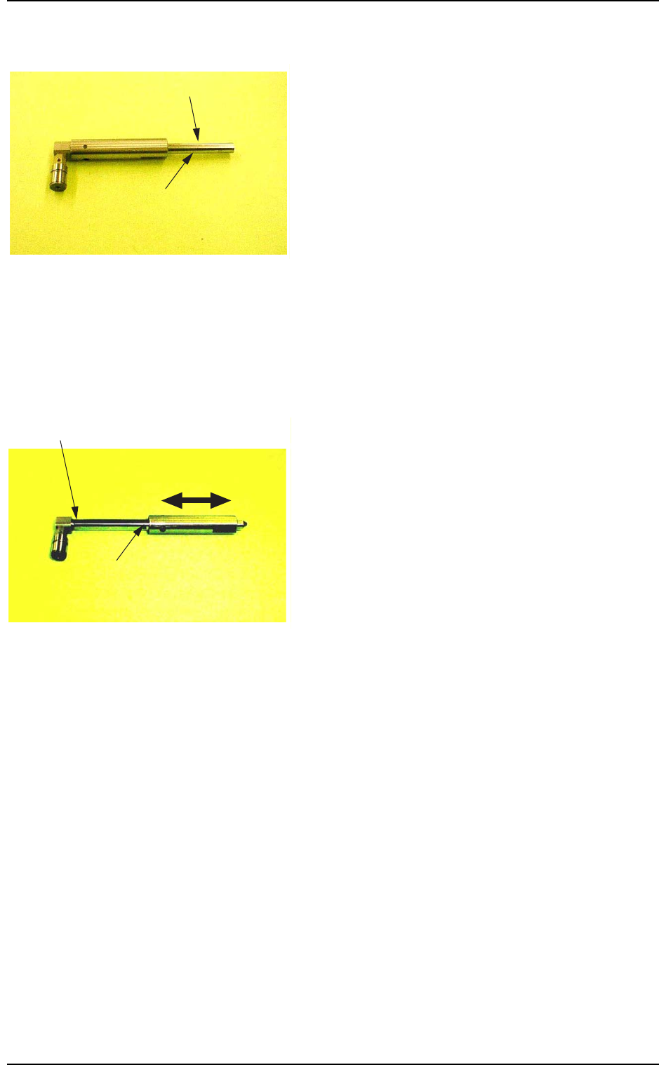
(2) Attach the MSB inserting jig to the shaft and
insert it into the outer cylinder.
Note: Do not change the combination of the
shaft and the outer cylinder.
(3) Apply “DAPHNE EPONEX GREASE No. 1”
thinly to the shaft and smooth out the grease
by rotating or moving the outer cylinder.
Note: Apply the grease to the upper surface of
the shaft such that the seals can also be
greased.
(4) Pull out the shaft from the outer cylinder with
the MSB inserting jig being attached.
01 10-003 1-58
AFO01ETRP
MSB Inserting Jig
Apply "DAPHNE EPONEX GREASE
No. 1" thinly to the lower surface.
Fig. 4A77
Apply "DAPHNE EPONEX GREASE No. 1"
thinly to the upper surface.
Rotate and move the outer
cylinder right and left.
Do not allow the grease
to flow into the hole.
Fig. 4A78
1.4 Maintenance Method
• Attachment of Miniature Stroke Bearing
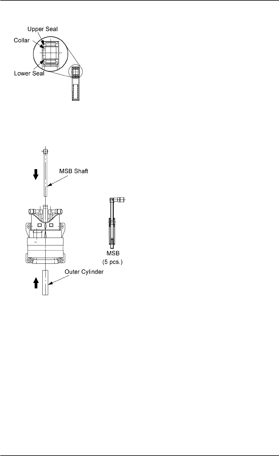
(1) Attachment of Seals and Collar to Outer
Cylinder of Miniature Stroke Bearing
(1-1) Wipe the seals with a dry cloth and apply
“DAPHNE EPONEX GREASE No. 1” to
the internal side of the seals.
(1-2) Attach the lower seal, the collar, and the
upper seal to the outer cylinder in this
order.
Note: Be sure to attach the seals and the
collar in the correct directions.
(2) Attachment of Miniature Stroke Bearing to
Head
(2-1) Insert the outer cylinder of the miniature
stroke bearing from under the head.
Note: Adjust the outer cylinder such that the
cutout faces inward.
(2-2) Insert the shaft from the top of the head
with the MSB inserting jig being attached.
(2-3) Detach the MSB inserting jig.
Note: If the jig is slippery, wipe it with a cloth
soaked in industrial alcohol.
(2-4) Attach the anchor plate to the outer cylin-
der and secure it with the screw (M3L10).
Apply “Screw Lock (1401B)” to the screw
and tighten it with a tightening torque of 7
kgfcm.
01 10-003 1-59
AFO01ETRP
Fig. 4A79
Fig. 4A80
1.4 Maintenance Method
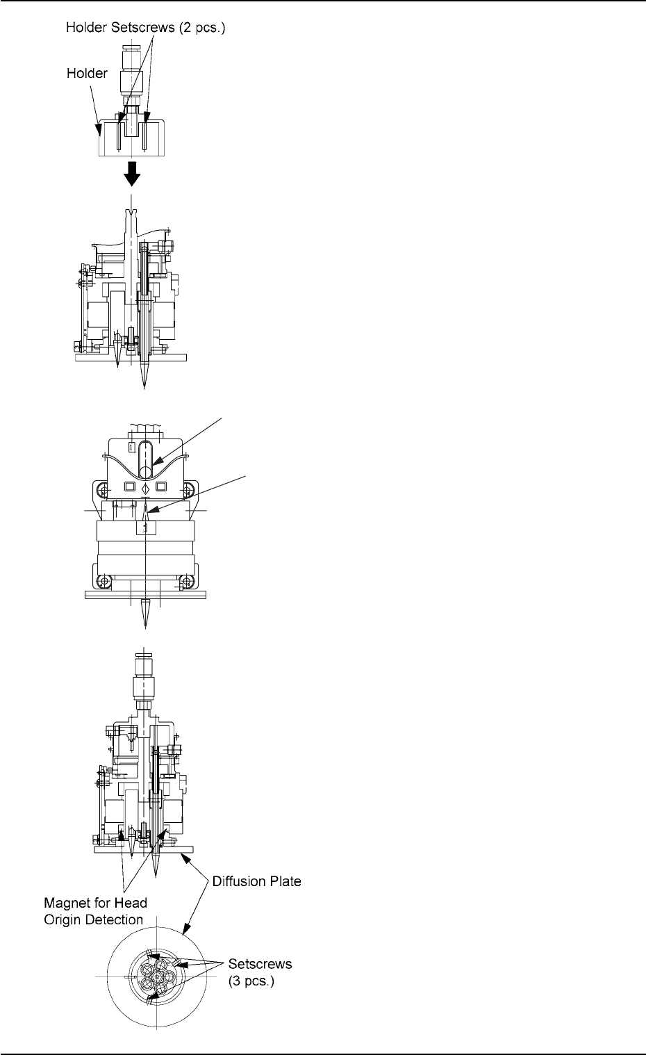
(3) Attachment of Holder to Head
(3-1) Apply “DAPHNE EPONEX GREASE No.
1” thinly to the bearing guide section of the
holder and the pin end.
(3-2) Match the holder guide with the cutout of
the head’s center shaft and insert the
holder into the top of the head.
(3-3) Push the holder into the shaft until it stops
and match the marker of the cam unit
with the center of the cam follower.
(3-4) Apply “Screw Lock (1401B)” to the set-
screws. After that, tighten the setscrews
with a tightening torque of 5 kgfcm.
(4) Attach the diffusion plate to the head and
secure it with three setscrews.
Note: There are two types of setscrews -
“Special Ones (Anti-Loosening Pro-
cessed Ones)” and “Normal Ones”.
Tighten the special setscrews with a
tightening torque of 10 kgfcm.
When the normal setscrews are used,
apply “Screw Lock (1401B)” to them and
tighten with a tightening torque of 5
kgfcm.
(5) Apply “DAPHNE EPONEX GREASE No. 1”
thinly to the cam face of the holder.
Fig. 4A81
Fig. 4A82
01 10-003 1-60
AFO01ETRP
1.4 Maintenance Method
Cam Follower
Marker of Cam Unit
Fig. 4A81-1