SC_450 PreciseCoat Conformal Coating Jet_Rev_04.pdf - 第13页
© 2024 Nordson Corporation 7 3 Installation and Con fig uration 3.1 Overview The SC-450 Pr eciseCoat Jet is des igned for use on Nor dson Select Coat Ser ies Coating Systems. This section includes t he fol l owing i nstr…
SC-450 PreciseCoat Conformal Coating Jet Safety
6 © 2024 Nordson Corporation
2.6 Disposal
Dispose of equipment and materials used in operation and servicing in accordance with local regulations.
Depending on the fluid dispensed and cleaning materials used, the following items may contain
substances whose disposal might be regulated:
• Dispensing Needles
• Fluid Body
• Fittings
2.7 Emergency Shutdown
In the event of an emergency or malfunction, press the Emergency Machine Off (EMO or E-Stop) button
on the coating system and perform the following steps:
• Disconnect and lockout system electrical power. Close hydraulic and pneumatic shutoff
valves and relieve pressure.
• Identify the reason for the malfunction and correct it before restarting the system.
2.8 Safety Warning Labels
Safety warning labels on your equipment point out areas where personnel must use extreme caution to
prevent serious injury and property damage. Refer to the applicable coating system Installation,
Operations, and Maintenance Manual for important safety information and coating system label locations.
WARNING!
Comply with all safety warning labels on the coating system and optional
equipment or serious injury to personnel or damage to the coating system may
occur. Replace worn or damaged labels.
© 2024 Nordson Corporation 7
3 Installation and Configuration
3.1 Overview
The SC-450 PreciseCoat Jet is designed for use on Nordson Select Coat Series Coating Systems. This
section includes the following instructions:
•
Unpacking the SC
-
450
•
Installing the
Fluid
Needle
•
Installing the
SC
-
450 PreciseCoat Jet
•
SC
-
450
EasyCoat Configuration
• Pneumatic, Electrical, and Fluid
Connections
3.2 Safety First
Operation of the SC-450 PreciseCoat Jet involves air pressure, electrical power, mechanical devices, and
the use of hazardous materials, and sometimes may involve heat. It is essential that every person
servicing or operating the applicator fully understands all hazards, risks, and safety precautions. See
Section 2 - Safety for additional information.
WARNING!
Allow only qualified personnel to perform the following tasks. Follow the safety
instructions in this document and all other related documentation.
WARNING!
Ensure the fluid system is completely depressurized prior to loosening any fittings
in the fluid path. Failure to do so may cause serious injury to personnel.
3.3 Unpacking the SC-450 PreciseCoat Jet
Every care has been taken when packaging the SC-450 PreciseCoat Jet. However, we recommend that
you look for obvious damage and verify contents against the packing slip.
Retain the case for storage of the SC-450 PreciseCoat Jet and accessories. Retain shipping cartons for
future use. If an item needs to be returned to Nordson, obtain a Return Material Authorization (RMA)
number from Technical Support, see 7.3 Parts Ordering Information.
SC-450 PreciseCoat Conformal Coating Jet Installation and Configuration
8 © 2024 Nordson Corporation
3.4 Installing the SC-450 PreciseCoat Jet
If the applicable applicator bracket is not installed on the Z-head, refer to the applicable coating system
Installation, Operations, and Maintenance Manual for installation.
Tools and Materials Needed:
•
Metric Allen Wrench Set
•
Torque Wrench (0
-
50 in
-
lbs)
3.4.1 Single Applicator Bracket
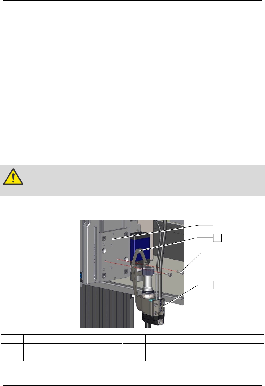
To install the applicator (Figure 3-1):
1. Verify coating system is turned off. Press the Stop button on the front panel.
2. Open the front hood of the coating system.
3. Manually move the dispense head to the front of the coating system.
4. Align the alignment hole on the mounting plate of the SC-450 to the locating pin on the
valve mount bracket.
5. Install the SC-450 to the valve mount bracket with two (2) screws.
6. Torque the two (2) screws to 2.82 Nm (25 in-lbs).
WARNING!
Before tightening the screws, verify the mounting plate and valve mount bracket
are flush with no gaps between them, or damage may occur.
7. Install the pneumatic, electrical, and fluid connections, see 3.5 Pneumatic, Electrical, and
Fluid Connections.
Item Description Item Description
1 Locating Pin 3 Screws (2)
2 Alignment Hole 4 SC-450
Figure 3-1 Installing the SC-450
1
2
3
4