SC_450 PreciseCoat Conformal Coating Jet_Rev_04.pdf - 第43页
SC-450 PreciseCoat C onformal C oating J et Maintenance and Service © 2024 Nordson Corporation 37 5.7.5 Replaci ng the Ne edle Shaft To remove the need le shaft: 1. Remove the SC-4 50 from the c oating system, see 5.6 Re…
SC-450 PreciseCoat Conformal Coating Jet Maintenance and Service
36 © 2024 Nordson Corporation
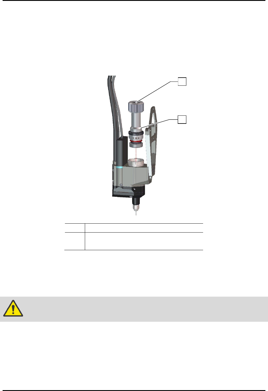
5.7.4 Replacing the Stroke Adjustment Assembly
To remove the stroke adjustment assembly (Figure 5-12):
1. Remove the SC-450 from the coating system, see 5.6 Removing the SC-450.
2. Using a hex wrench, unscrew the stroke adjustment assembly from the valve body
assembly.
3. Remove the stroke adjustment assembly.
Item Description
1 Location of Hex Screw
2 Stroke Assembly (Item 1)
Figure 5-12 Replacing the Stroke Assembly
To install the stroke assembly (Figure 5-12):
1. Apply a light coating of dry film paste lubricant (Item 23) to the detent balls on the stroke
adjustment assembly.
WARNING!
Failure to lubricate the detent balls will lead to rapid wearing of parts and failure.
2. Using a hex wrench, reinstall the stroke adjustment assembly onto the jet body.
3. Install the SC-450 to the coating system, see 3.4 Installing the SC-450 PreciseCoat Jet.
4. Set the stroke adjustment, see 4.4.5 Stroke Adjustment.
2
1
SC-450 PreciseCoat Conformal Coating Jet Maintenance and Service
© 2024 Nordson Corporation 37
5.7.5 Replacing the Needle Shaft
To remove the needle shaft:
1. Remove the SC-450 from the coating system, see 5.6 Removing the SC-450.
2. Remove the needle assembly, see 5.5.1 Cleaning and Replacing the Fluid Needle.
3. Remove the heater assembly and fluid body, see 5.7.1 Removing and Replacing the Heater
Assembly, Fluid Body, and Fluid Seal.
4. Remove the stroke adjustment assembly, see 5.7.4 Replacing the Stroke Adjustment
Assembly.
5. From the bottom of the valve body, push the needle shaft through the valve and out the top
of the chamber.
To install the needle shaft:
?
NOTE
The needle insertion tool (Item 23) can be used to assist with needle replacement.
1. Apply a light coating of dry film paste lubricant (Item 23) to the shaft and seal of the nozzle
assembly.
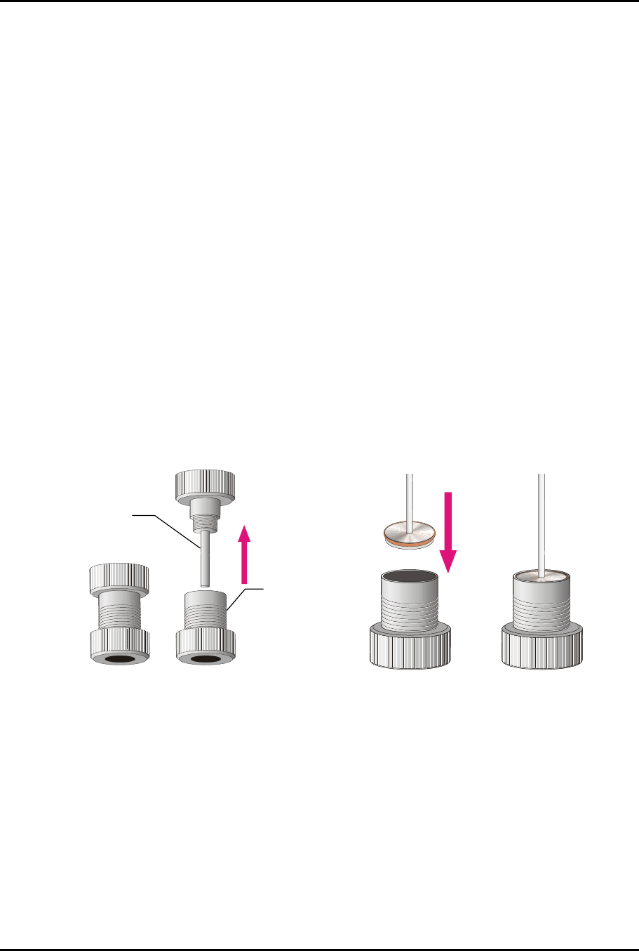
2. Unscrew and separate the needle insertion tool base and pin (Figure 5-13).
3. Insert the needle flange into the insertion tool base (Figure 5-14).
> The needle flange should audibly snap into place when new. The flange should rest just
below flush with the edge of the base.
Figure 5-13
Unscrewing the Needle Assembly
Figure 5-14
Inserting the Needle Flange
Base
Pin
SC-450 PreciseCoat Conformal Coating Jet Maintenance and Service
38 © 2024 Nordson Corporation
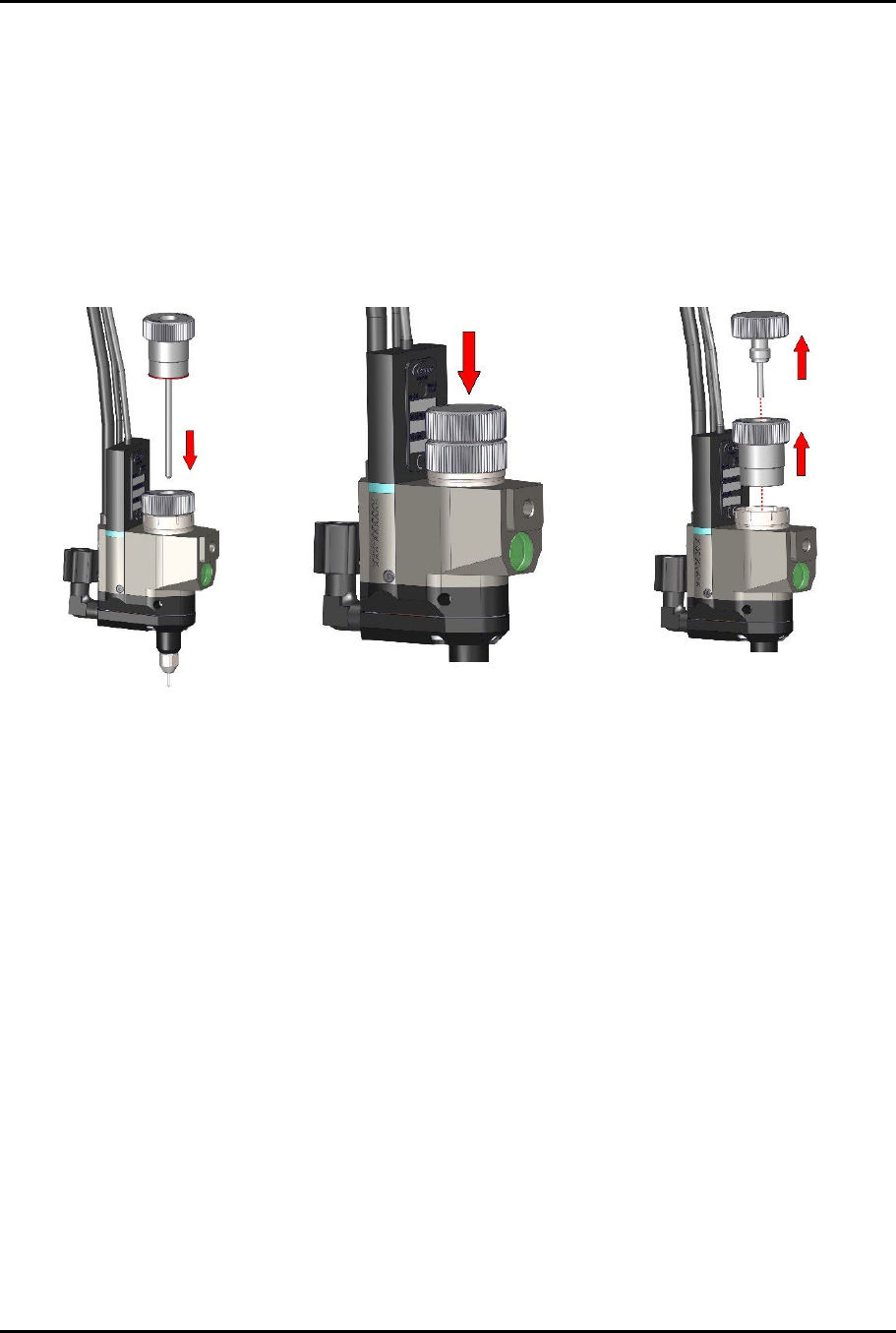
4. Line up the needle with the seal (Figure 5-15A).
5. Slide the needle through the bearings and slide the insertion tool base into the valve body.
6. Hand-tighten the base until it stops against the valve body.
7. Line up the installation pin with the hole in the top of the base (Figure 5-15A).
8. Push the pin all the way into the base (Figure 5-15B).
9. Remove the pin (Figure 5-15C).
10. Unscrew and remove the base from the valve body (Figure 5-15C).
Figure
5
-
15
A
Figure
5
-
15
B
Figure
5
-
15
C
Figure
5
-
15
Detaching the Needle from the Insertion Tool Base