SC_450 PreciseCoat Conformal Coating Jet_Rev_04.pdf - 第36页
SC-450 PreciseCoat C onformal C oating J et Maintenance and Service 30 © 2024 Nordson Corporation 5.7 Replacing SC-450 Components Tools and Materi als Needed: • Metric Al l en Wr ench Set • Shipping Kit ( Item 23 ) • Dry…
SC-450 PreciseCoat Conformal Coating Jet Maintenance and Service
© 2024 Nordson Corporation 29
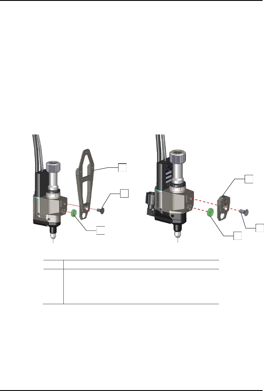
5. If the muffler requires replacement, follow the below steps (Figure 5-6):
a. Verify the coating system is turned off. Press the Stop button on the front panel.
b. Open the front hood of the coating system.
c. Manually move the dispense head to the front of the coating system.
d. Remove one (1) screw securing the bracket to the SC-450.
e. Remove the bracket from the SC-450.
f. Discard the muffler disc.
g. Install a new muffler disc.
h. Install one (1) screw securing the bracket to the SC-450.
?
NOTE
Ensure the muffler is installed into the valve body assembly of the SC-450.
i. Torque the screw to 2.82 Nm (25 in-lbs).
6. Install SC-450, see 3.4 Installing the SC-450 PreciseCoat Jet.
Fixed Option
Tilt and Rotate Option
Item Description
1 Bracket, Mounting (Item 4)
2 Screw, M5 x 10 mm, FSHC, Alloy
3 Muffler, 40 um, Disc, .5in OD, .125in THK (Item 8)
4 Bracket, Mounting, T&R (Item 7)
Figure 5-6 Installing the SC-450 to the Bracket
3
2
1
3
2
4
SC-450 PreciseCoat Conformal Coating Jet Maintenance and Service
30 © 2024 Nordson Corporation
5.7 Replacing SC-450 Components
Tools and Materials Needed:
•
Metric Allen Wrench Set
•
Shipping Kit (
Item 23
)
•
Dry Film Paste
Lubricant (
Item 23
)
•
Torque Wrench (0
-
5
0 in
-
lbs)
5.7.1 Removing and Replacing the Heater Assembly, Fluid Body, and Fluid Seal
To remove the heater assembly:
1. Remove the needle assembly, see 5.5.1 Cleaning and Replacing the Fluid Needle and
perform Step 1 through Step 6.
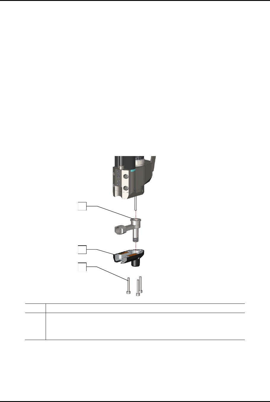
2. Remove three (3) screws securing the heater assembly to the valve body assembly
(Figure 5-7).
?
NOTE
When the screws are removed from the valve body, the fluid body will be loose
and may separate.
3. Remove the heater assembly.
Item Description
1 U-Cup, VSPG, 2 LIP, PI-PTFE, 1/8 Rod (Items 19 and 23) (U-cup is inside)
2 Assy, Heater, 24W (Item 17)
3 Screw, M3 x 0.5 x 16, SHCS, SS (Items 18 and 23)
Figure 5-7 Replacing the Heater Assembly
3
2
1
SC-450 PreciseCoat Conformal Coating Jet Maintenance and Service
© 2024 Nordson Corporation 31
4. Inspect the U-cup seal in the fluid path on the inside bottom of the fluid body assembly.
> Do not remove the U-cup seal unless the U-cup seal is damaged or fluid leaks from the
body weep hole.
WARNING!
The U-cup seal may become damaged during removal causing fluid to leak from
the SC-450. Do not re-use the U-cup seal once it has been removed from the
SC-450.
a. If damaged, use the seal removal tool to remove the U-cup seal from the bottom of the
fluid body assembly.
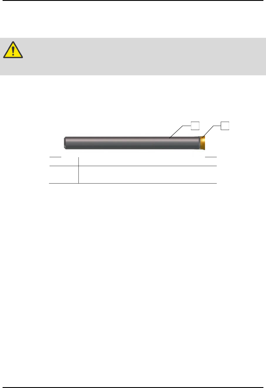
b. Install a new U-cup seal by placing the U-cup seal on the end of the seal press tool
supplied in the shipping kit (with the side containing the spring facing outward)
(Figure 5-8).
Item Description
1 Seal Press Tool (Item 23)
2 U-Cup Seal (Items 19 and 23)
Figure 5-8 Utilizing the Seal Press Tool
c. Insert the seal press tool into the fluid body assembly (Figure 5-9).
d. Ensure the seal press tool is seated at the bottom of the chamber.
e. Push down on the seal press tool to seat the U-cup seal into the chamber.
> The U-cup seal should snap into place.
?
NOTE
When replacing the U-cup seal, it is recommended to cycle the SC-450 with solvent at
zero (0) psi fluid pressure for 10,000 cycles.
1
2