SC_450 PreciseCoat Conformal Coating Jet_Rev_04.pdf - 第41页
SC-450 PreciseCoat C onformal C oating J et Maintenance and Service © 2024 Nordson Corporation 35 To install the solenoid (Figure 5-11): WARNING! Special care shou l d be ta ken when handling O- ri ngs and sea ls. If O-r…
SC-450 PreciseCoat Conformal Coating Jet Maintenance and Service
34 © 2024 Nordson Corporation
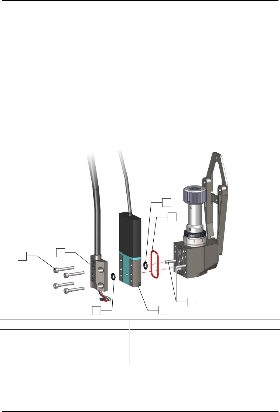
5.7.3 Replacing the Solenoid Valve
The solenoid valve and associated parts are part of the cable with solenoid assembly (Item 12).
To remove the solenoid valve (Figure 5-11):
1. Remove the SC-450 from the coating system, see 5.6 Removing the SC-450.
2. Remove the heater assembly and separate the fluid body and and heater insulation from
the valve body, see 5.7.1 Removing and Replacing the Heater Assembly, Fluid Body, and
Fluid Seal.
3. Remove the four (4) screws from the junction plate.
4. Separate the junction plate and 3-way valve from the valve body assembly.
5. Remove and set aside the two (2) O-rings (Items 11 and 23).
6. Remove and set aside the O-ring (Items 10 and 23).
Item Description Item Description
1
Screw, M3 x 0.5 x 16 SHCS, SS
(part of Item 12)
4 Assy, Cable w/Solenoid (Item 12)
2 Plate, Junction (part of Item 12) 5 O-Ring, 020, Viton (Items 10 and 23)
3 O-Ring (Items 11 and 23) 6 Dowel Pins
Figure 5-11 Replacing the Solenoid Valve Assembly
1
3
4
2
5
3
6

SC-450 PreciseCoat Conformal Coating Jet Maintenance and Service
© 2024 Nordson Corporation 35
To install the solenoid (Figure 5-11):
WARNING!
Special care should be taken when handling O-rings and seals. If O-rings and
seals are damaged, the film coater may leak or fail prematurely.
1. Apply a thin coat of lubricant to new O-rings (Items 10, 11, and 23).
2. Install the O-rings into the valve body assembly.
3. Slide the solenoid onto the dowel pins extruding from the valve body assembly.
4. Apply a thin coat of dry paste lubricant (Item 23) to a new O-ring (Items 11 and 23).
5. Insert the O-ring (Items 11 and 23) into the rear of the junction plate.
6. Install the junction plate onto the dowel pins extruding from the valve body assembly.
> Ensure the control cable is fully seated into the groove of the junction plate.
7. Install four (4) screws securing the junction plate and 3-way valve onto the valve body
assembly.
8. Install the SC-450, see 3.4 Installing the SC-450 PreciseCoat Jet.
SC-450 PreciseCoat Conformal Coating Jet Maintenance and Service
36 © 2024 Nordson Corporation
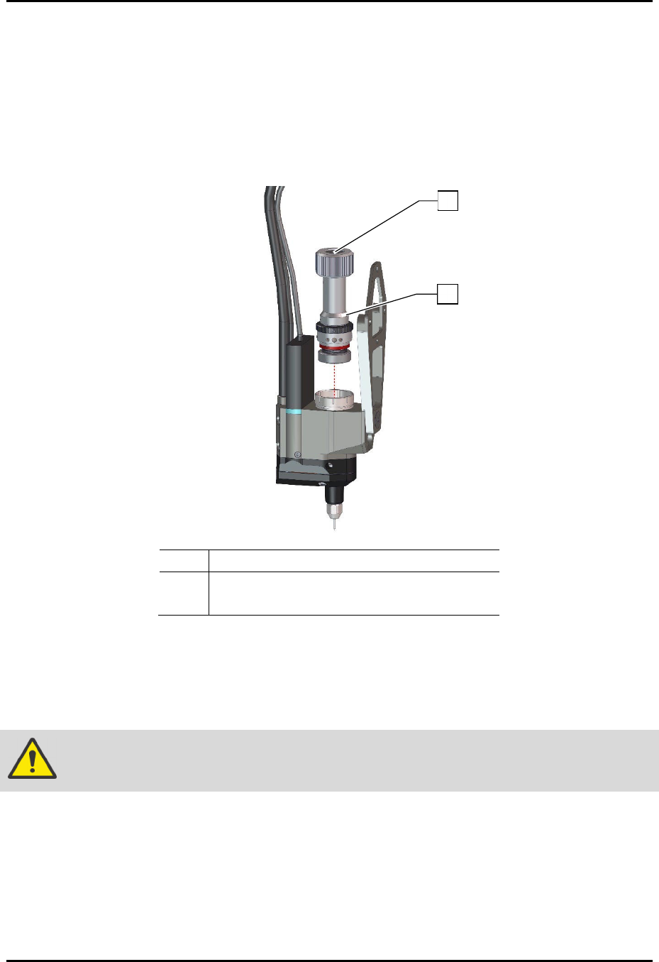
5.7.4 Replacing the Stroke Adjustment Assembly
To remove the stroke adjustment assembly (Figure 5-12):
1. Remove the SC-450 from the coating system, see 5.6 Removing the SC-450.
2. Using a hex wrench, unscrew the stroke adjustment assembly from the valve body
assembly.
3. Remove the stroke adjustment assembly.
Item Description
1 Location of Hex Screw
2 Stroke Assembly (Item 1)
Figure 5-12 Replacing the Stroke Assembly
To install the stroke assembly (Figure 5-12):
1. Apply a light coating of dry film paste lubricant (Item 23) to the detent balls on the stroke
adjustment assembly.
WARNING!
Failure to lubricate the detent balls will lead to rapid wearing of parts and failure.
2. Using a hex wrench, reinstall the stroke adjustment assembly onto the jet body.
3. Install the SC-450 to the coating system, see 3.4 Installing the SC-450 PreciseCoat Jet.
4. Set the stroke adjustment, see 4.4.5 Stroke Adjustment.
2
1