SC_450 PreciseCoat Conformal Coating Jet_Rev_04.pdf - 第23页
SC-450 PreciseCoat C onformal C oating J et Operation © 2024 Nordson Corporation 17 4.5.1 Fi ne Tuned Settings For volumetric repeat ability applications, the following parameters will help decrease re peatability. Table…

SC-450 PreciseCoat Conformal Coating Jet Operation
16 © 2024 Nordson Corporation
4.4.4 Solenoid Valve
The solenoid valve controls the valve operation. When energized, it allows air into the piston chamber to
compress a spring and thereby raise the needle assembly. When de-energized, the air is released and
the spring forces the piston down so that the needle tip contacts the seat. The valve ON/OFF times can
be adjusted in the EasyCoat software.
4.4.5 Stroke Adjustment
The stroke adjustment controls the travel distance of the needle or nozzle assembly. Turn
counterclockwise to increase needle or nozzle assembly travel, turn clockwise to decrease travel. Stroke
is directly proportional to closing velocity of the drive needle.
To set the stroke stop:
1. Tighten the stroke adjustment knob all the way down until stopped.
2. Back the stroke adjustment knob out to required setting.
4.4.6 Heater Temperature
Fluid temperature is used for process stability. Set the fluid temperature 5-10° above room temperature.
Adjusting the fluid temperature higher can be used to help dispense higher viscosity fluids.
Most conformal coating materials have solvents, even 100% solids have solvents.
WARNING!
Use caution when setting above 45ºC. Solvents will boil in the fluid chamber
causing internal failure.
4.5 Application Settings
Table 4-1 Sample Application Settings - Lines (Spacing Mode)
Initial Settings
Comments
Category
Settings
Unit
Fluid
Viscosity
25
600
1200
cps
Valve Pressure
80 (SL-940)
Main Air (SL-1040)
psi The parameter does not require adjustment.
Stroke
Adjustment
5 20 25 graduations
• If fluid is accumulating on needle tip, increase stroke.
• If fluid is atomizing (satellites), decrease stroke.
•
Use a large
stroke setting
for a
tighter volumetric repeatability
.
Fluid Pressure 5 30 60 psi
• Use higher fluid pressure for tighter volumetric repeatability.
Heater
Temperature
35 °C
• Set 5 - 10° above room temperature to be used for process
stability.
Valve Timing 3 On / 3 Off ms
• Minimum On/Off Time is 3/3 ms.
• Position based timing is recommended.
•
Zero Start and Stop Distances is recommended.
Dispense Height 2 mm
Adjust the height to lowest possible without part interference.
Lower heights are more repeatable and help prevent accumulation
during production.
Drive Needle
Φ
6.4
mm
See Item 20.
Fluid Needle 150 um or 22 ga um See Items 21 and 22.

SC-450 PreciseCoat Conformal Coating Jet Operation
© 2024 Nordson Corporation 17
4.5.1 Fine Tuned Settings
For volumetric repeatability applications, the following parameters will help decrease repeatability.
Table 4-2 Volumetric Repeatability Factors
Parameter
Action
Shot Size Increase
Stroke
Decrease
Fluid
Pressure
Increase
On Time
Increase
For noise sensitive applications, the following parameters will help reduce audible noise levels.
Table 4-3 Audible Noise Factors
Parameter
Action
Drive
Needle
Q type Needles (
See
Item 20
)
Stroke Decrease
Drive Frequency 145Hz (3ms On/3.8 Off)
4.6 Hardware Selection
Hardware selection is based on multiple factors and the values are application dependent. These are
Asytmek starting points, contact Technical Support for additional information.
The SC-450 can be configured for two (2) different needle types, other needle types are not supported.
Utilize Table 4-4 to assist with the needle types.
Table 4-4 Needle Types
DL Type Needle Hubbed Nozzle
Precision Applications
Accessibility Applications
Higher Viscosity
Lower Viscosity
Small Dots and Lines
Larger Dots and Lines
1.5 - 3 mm Line Widths 2.5 - 3.5 mm Lines and Widths
6 mm
Component Clearance
12 mm
Component Clearance
SC-450 PreciseCoat Conformal Coating Jet Operation
18 © 2024 Nordson Corporation
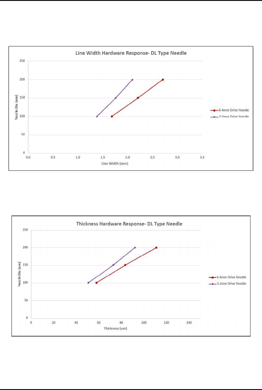
4.6.1 DL Type Needle Hardware Response
To determine hardware response:
1. Utilize Figure 4-1 to determine the nozzle diameter based off the targeted line width.
Figure 4-1 Line Width
2. Utilize Figure 4-2 to estimate thickness of coating based on the selected nozzle diameter.
?
NOTE
Thickness increases with line width and is application dependent.
Figure 4-2 Thickness