SC_450 PreciseCoat Conformal Coating Jet_Rev_04.pdf - 第21页
© 2024 Nordson Corporation 15 4 Operati on 4.1 Overview This SC-450 Pr eciseCoat Jet is desig ned for use on Nords on Sel e c t Coat Series Coating Systems. F or complete system operati ng procedures, re fe r to the appl…
SC-450 PreciseCoat Conformal Coating Jet Installation and Configuration
14 © 2024 Nordson Corporation
5. Select the SC-450 tool.
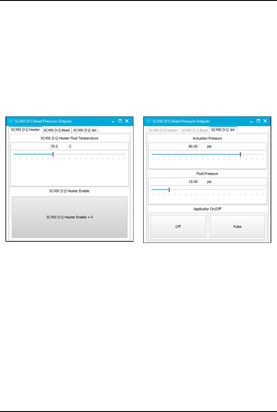
> The Pressure Outputs window opens.
6. Slide the pressure bars to achieve the suggested starting pressures (Figure 3-8):
a. Set Heater Fluid Temperature to 35 °C.
b. Choose one of the two (2) operating modes SC450 Bead or SC450 Jet.
1) Set Actuation Pressure to 551 kPa (80 psi).
2) Set Fluid Pressure to 103 kPa (15 psi).
c. Set stroke to 25 clicks open.
7. Perform a priming routine. Refer to the applicable coating system Installation, Operations,
and Maintenance Manual.
Figure 3-7 Pressure Outputs
© 2024 Nordson Corporation 15
4 Operation
4.1 Overview
This SC-450 PreciseCoat Jet is designed for use on Nordson Select Coat Series Coating Systems. For
complete system operating procedures, refer to the applicable coating system Installation, Operations,
and Maintenance Manual. This section covers the following topics:
•
Theory of Operation
•
Application Settings
•
Control
Components
•
Hardware Selection
4.2 Safety First
Operation of the SC-450 PreciseCoat Jet involves air pressure, electrical power, mechanical devices, and
the use of hazardous materials, and sometimes may involve heat. It is essential that every person
servicing or operating the PreciseCoat Jet fully understands all hazards, risks, and safety precautions.
See Section 2 - Safety for additional information.
WARNING!
Allow only qualified personnel to perform the following tasks. Follow the safety
instructions in this document and all other related documentation.
4.3 Theory of Operation
The SC-450 PreciseCoat Jet is a normally closed, air-actuated, spring-return mechanism, which uses
momentum transfer principles to expel precise volumes of material. Pressurized air is regulated by a high-
speed solenoid to retract the needle assembly from the seat. Fluid, fed into the fluid chamber, flows over
the seat. When the air is exhausted, the needle travels rapidly to the closed position, displacing fluid
through the seat and nozzle in the form of a droplet. Multiple droplets fired in succession can be used to
form larger dispense volumes and lines when combined with the motion of a dispenser robot.
4.4 Control Components
The following features affect performance of the SC-450 and are typically adjusted to fit your application.
Contact Technical Support for additional information.
4.4.1 Dot and Line Parameters
In addition to the SC-450 hardware configuration and settings, valve timing and coating instructions are
set in the EasyCoat software program to control the frequency and speed of dots and lines dispensed.
For information on dispense parameters, refer to the EasyCoat User Guide or EasyCoat Help.
4.4.2 Fluid Pressure
Fluid pressure should be set so that fluid fills to the seat, but should not be influential in pushing the fluid
through the seat and nozzle. In general, fluid pressure should be set according to the viscosity of the fluid
dispensed, see Table 4-1.
4.4.3 Drive Needle and Fluid Needle
Drive needle and fluid needle geometries are typically the main factors controlling volume. Size is
determined based on fluid properties. Other parameters, like stroke and fluid pressure fine tune the
application. Sizes are listed in Item 20 through Item 22.
SC-450 PreciseCoat Conformal Coating Jet Operation
16 © 2024 Nordson Corporation
4.4.4 Solenoid Valve
The solenoid valve controls the valve operation. When energized, it allows air into the piston chamber to
compress a spring and thereby raise the needle assembly. When de-energized, the air is released and
the spring forces the piston down so that the needle tip contacts the seat. The valve ON/OFF times can
be adjusted in the EasyCoat software.
4.4.5 Stroke Adjustment
The stroke adjustment controls the travel distance of the needle or nozzle assembly. Turn
counterclockwise to increase needle or nozzle assembly travel, turn clockwise to decrease travel. Stroke
is directly proportional to closing velocity of the drive needle.
To set the stroke stop:
1. Tighten the stroke adjustment knob all the way down until stopped.
2. Back the stroke adjustment knob out to required setting.
4.4.6 Heater Temperature
Fluid temperature is used for process stability. Set the fluid temperature 5-10° above room temperature.
Adjusting the fluid temperature higher can be used to help dispense higher viscosity fluids.
Most conformal coating materials have solvents, even 100% solids have solvents.
WARNING!
Use caution when setting above 45ºC. Solvents will boil in the fluid chamber
causing internal failure.
4.5 Application Settings
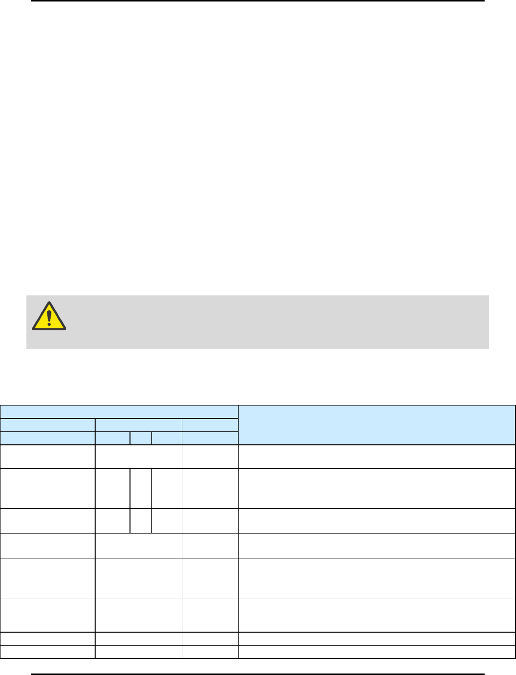
Table 4-1 Sample Application Settings - Lines (Spacing Mode)
Initial Settings
Comments
Category
Settings
Unit
Fluid
Viscosity
25
600
1200
cps
Valve Pressure
80 (SL-940)
Main Air (SL-1040)
psi The parameter does not require adjustment.
Stroke
Adjustment
5 20 25 graduations
• If fluid is accumulating on needle tip, increase stroke.
• If fluid is atomizing (satellites), decrease stroke.
•
Use a large
stroke setting
for a
tighter volumetric repeatability
.
Fluid Pressure 5 30 60 psi
• Use higher fluid pressure for tighter volumetric repeatability.
Heater
Temperature
35 °C
• Set 5 - 10° above room temperature to be used for process
stability.
Valve Timing 3 On / 3 Off ms
• Minimum On/Off Time is 3/3 ms.
• Position based timing is recommended.
•
Zero Start and Stop Distances is recommended.
Dispense Height 2 mm
Adjust the height to lowest possible without part interference.
Lower heights are more repeatable and help prevent accumulation
during production.
Drive Needle
Φ
6.4
mm
See Item 20.
Fluid Needle 150 um or 22 ga um See Items 21 and 22.