OM-1273-004_w.pdf - 第125页
3-16 AJK-ML T-ID 4.2 Auto Operation 4.2.1 T ray matrix update setup When the "T ray Matrix Update Setup" subtab is pressed in the "Auto Operation" tab sheet, the following subtab sheet appears. Fig. C…
3-15
AJK-MLT-ID
(5) Magazine #2
The upper magazine in the elevator unit can be adjusted.
Parameters can be specied in the "Rack position [mm]", "Rack
position (Center) [mm]", "Rack draw level [mm]", and "Rack putback
level [mm]" text boxes as Magazine #2 Offsets.
Rack position [mm]
This offset data can be used to adjust the loading position of Magazine
#2.
Note
Follow the same adjustment as taken for the setup position of
Magazine #1 to obtain the numerical values and perform the
adjustment based on the obtained values.
Rack position (Center) [mm]
This offset data can be used to adjust the magazine change position.
Note
Follow the same adjustment as taken for the setup position of
Magazine #1 to obtain the numerical values and perform the
adjustment based on the obtained values.
Rack draw level [mm]
This offset data is used to align the traverse chute in height with the
step (stage) of the tray when a pallet is drawn from Magazine #2 to the
traverse chute.
Note
Follow the same procedure as described for "Rack draw level [mm]"
of Magazine #1.
Rack putback level [mm]
This offset data is used to align the traverse chute in height with the step
(stage) of the tray when a pallet is put back from the traverse chute to
Magazine #2.
Note
Follow the same procedure as described for "Rack putback level
[mm]" of Magazine #1.
4.1 Offset Data
0706-002
3-16
AJK-MLT-ID
4.2 Auto Operation
4.2.1 Tray matrix update setup
When the "Tray Matrix Update Setup" subtab is pressed in the "Auto
Operation" tab sheet, the following subtab sheet appears.
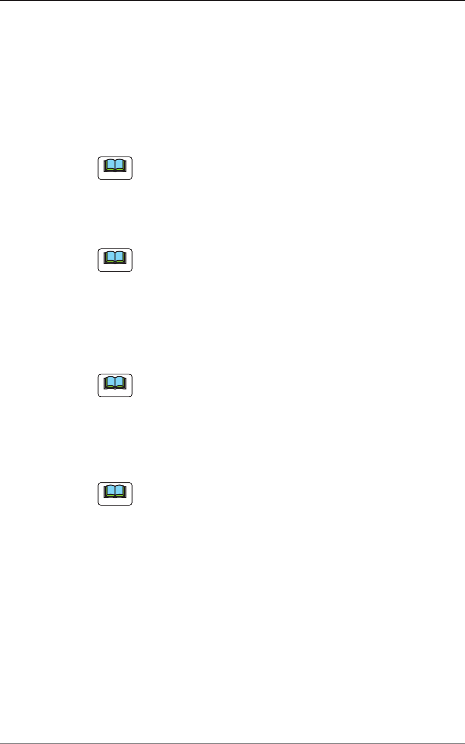
Fig. C10 "Tray Matrix Update Setup" Subtab Sheet
(1) Tray matrix update setup
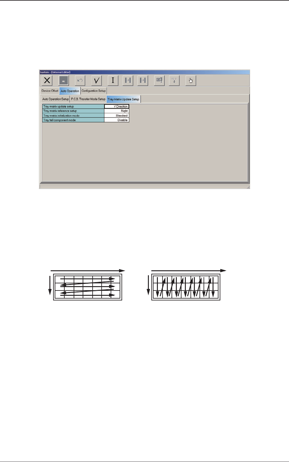
Select "X Direction" or "Y Direction" (direction in which components
should be taken out) in the text box.
In normal cases, "Y Direction" should be selected.
X
Y
Y
Selection of "Y Direction"Selection of "X Direction"
X
Fig. C11
4.2 Auto Operation
0804-003
3-17
AJK-MLT-ID
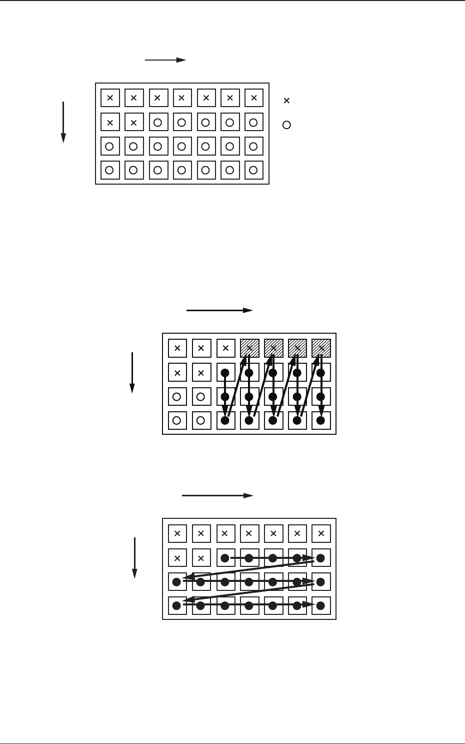
For example :
The tray is in the condition as shown in Fig. C12.
(Tray in Middle of Process)
1
1
2
99
2 3 99
X
Y
: No Component
(Taken Out)
: Component Existing
.
.
.
. . . . . .
Fig. C12
•
The rst component pick-up position is assumed to be "X: 3, Y: 2".
: Component Picked Normally
: Component Left Behind
Shadowed :
Mispick
1
1
2
99
2 3 99
X
Y
.
.
.
. . . . . .
Selection of "Y Direction"
Fig. C13
1
1
2
99
2 3 99
X
Y
.
.
.
. . . . . .
Selection of "Y Direction"
Fig. C14
4.2 Auto Operation
0706-002