OM-1273-004_w.pdf - 第49页
1-12 AJK-ML T-ID 0706-002 3.1 Layout of Main Machine C A U T I O N Do not bring a magnetic card or a watch close the tray magnets. Otherwise, the data of the magnetic card might be cleared or a watch, etc., may be damage…
1-11
AJK-MLT-ID
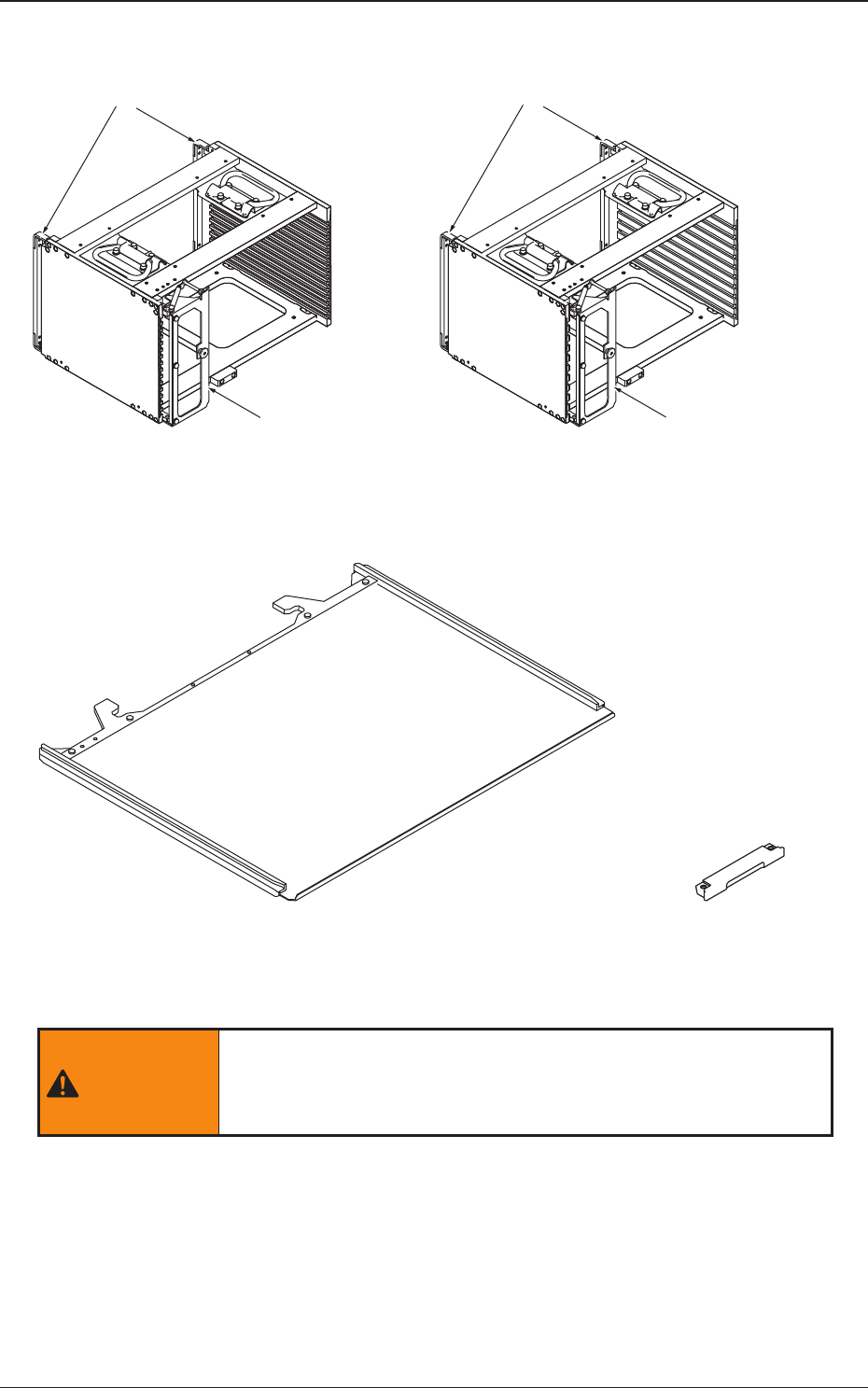
Rack Shutter
Rack Shutter
MG-G110MG-G115
Magazine Door Magazine Door
Fig. A2 Magazine
Pallet (MP-G100)
Tray Magnet
(MF-G100)
Fig. A3 Pallet and Tray Magnet
WARNING
Do not bring the tray magnet close to the area where a
pacemaker is implanted. Otherwise, the pacemaker may be
affected by the magnetism and a serious accident will result.
0706-002
3. Name of Each Section and Handling
1-12
AJK-MLT-ID
0706-002
3.1 Layout of Main Machine
CAUTION
Do not bring a magnetic card or a watch close the tray magnets.
Otherwise, the data of the magnetic card might be cleared or a watch,
etc., may be damaged due to the strong magnetism.
Handle the pallets carefully.
Otherwise, the pallets may be deformed.
·
Do not drop the pallet onto the oor, etc.
·
Do not apply any force partially to any area of the pallet.
·
Do not store the pallets in a pile.
When a deformed pallet is used, a component pickup error may occur.
When a component pickup error occurs frequently, replace the pallet
with a new one.
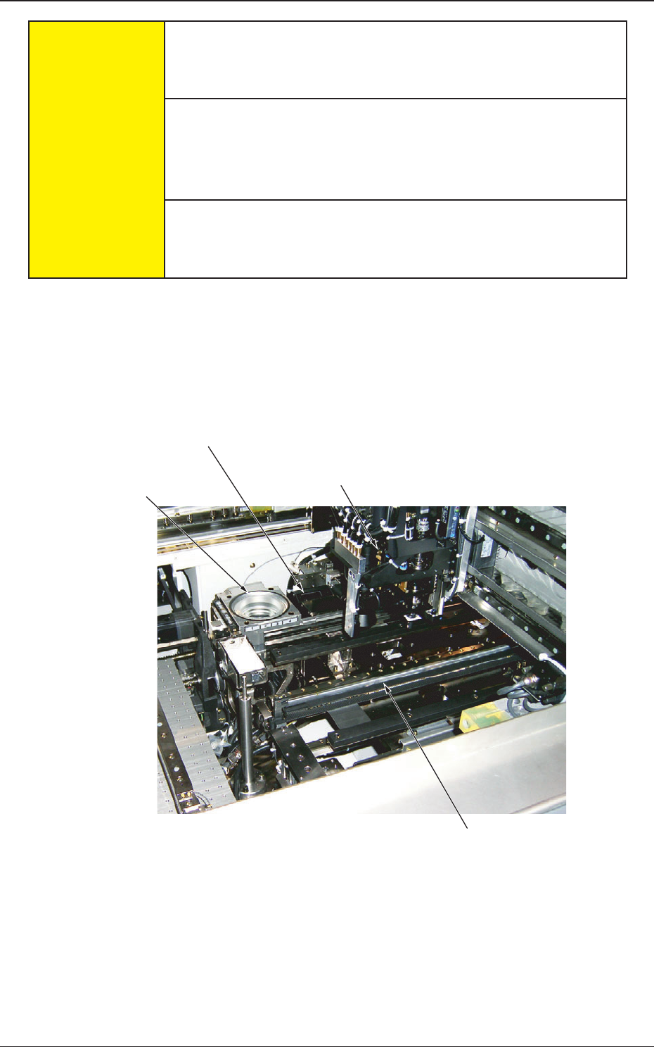
3.1 Layout of Main Machine
When "FP-G200" is installed on the main machine, the layout of the installed
stage will be changed.
Component Recognition
Camera
Coplanarity
Check Unit (Option)
Placement Head (Multifunctional Head (Option))
Traverse
Fig. A4
1-13
AJK-MLT-ID
0706-002
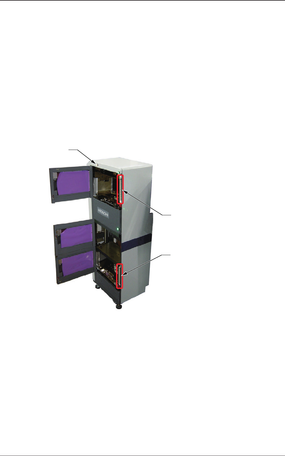
3.2 Elevator
The elevator is provided with a mechanism that moves the magazines up and
down.
The elevator can be loaded with two magazines in which the pallets are
stored. Each magazine is driven up and down separately.
The trays on the pallets in each magazine can be replenished with
components or the trays on each pallet can be reloaded with components at
the specied position.
The magazines can manually be attached to or detached from the elevator.
The magazine loaded on the elevator is clamped with a spring force and
positioned in place.
Lower [ALL CHANGE] Button and
Step No. Buttons ([1] through [15])
Elevator Power LED
Upper [ALL CHANGE] Button and
Step No. Buttons ([1] through [15])
Fig. A5
(1) Elevator Power LED
This LED indicates whether or not the elevator is powered.
When the elevator is powered, the LED illuminates.
3.2 Elevator