mi17050592.pdf - 第15页
Micromachines 2026 , 17 , 592 15 of 34 3.3.3. Algorithm V erification A Headless Aligner script replicates the logic of the main controller . It loads each of the 9 mock files as a virtual device (simulating slew rates and…
Micromachines 2026, 17, 592
14 of 34
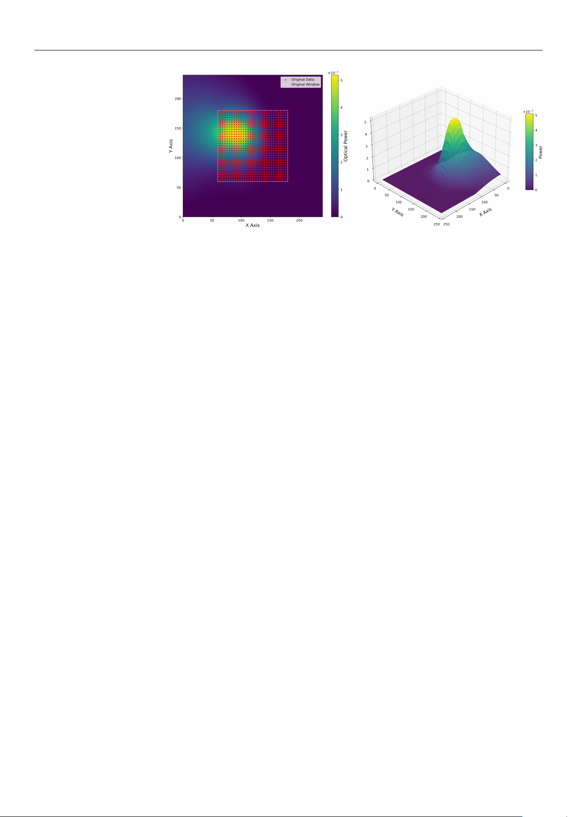
(a) (b)
Figure 6. Reconstructed optical power surface from experimental data. (a) 2D heatmap showing the
240
×
240 global grid with centered experimental data points (red markers within dashed rectangle).
(b) 3D surface visualization showing the smooth RBF interpolation and peak power region. The
surface extends beyond the measured region to create multiple mock test scenarios.
3.3.2. Environmental Simulation (Mock Scan Generation)
Real alignment hardware has a limited field of view corresponding to the piezoelectric
actuator range (120 V, equivalent to 15
µ
m displacement), while the simulated surface
is 240 units wide. To test algorithm robustness, the large surface is divided into smaller,
realistic views using a systematic sliding window technique, according to the following.
1.
Sliding Window Process: The sliding window process employs a fixed window size
of 120
×
120 units, which corresponds directly to the typical 0–120 V operating
range of the piezoelectric stage. To systematically evaluate the data, this window is
translated across the global 240
×
240 data matrix using a discrete step size of 60 units.
Originating at the (0, 0) coordinate of the global grid, the window slides through
sequential positions, such as (0, 60), (0, 120), and (60, 0), ensuring comprehensive and
overlapping coverage of the entire surface area in a structured grid pattern.
2.
Coordinate Localization: As the window moves to different positions (e.g., Global
X = 60 to 180), the system transforms the extracted data back to local coordinates
(0–120 V) by subtracting the offset from the window origin. This is critical, as it
ensures that the algorithms perceive every file as a standard 0–120 V hardware range,
indistinguishable from real operation.
3.
Mock File Generation: This systematic windowing process generates 9 distinct mock
CSV files from each experimental dataset. Each file contains only the X, Y, and Power
data visible within that specific 120 V
×
120 V window at offsets of 0, 60, and 120 V
in both dimensions. This forces the algorithms to locate the peak in various contexts
(e.g., peak centered, peak at the edge, or low-power regions), providing a rigorous
test of algorithm robustness across diverse initial conditions.
To provide a statistically rigorous benchmark, a comprehensive simulation library was
constructed from the 8 experimental datasets. Each experimental scan was interpolated
onto a 240
×
240 voltage grid using a multiquadric RBF to serve as a ground-truth coupling
landscape. From these, a total of 72 unique test scenarios (8 experiments
×
9 systematic
spatial offsets) were generated by extracting 120 V
×
120 V sub-windows at varying spatial
positions (offsets of 0, 60, and 120 V in each dimension). This systematic procedure ensures
that the algorithms are evaluated against a diverse set of initial peak positions relative to
the scan window, simulating a wide range of initial fiber-to-chip misalignments that might
occur in production testing.
https://doi.org/10.3390/mi17050592

Micromachines 2026, 17, 592
15 of 34
3.3.3. Algorithm Verification
A Headless Aligner script replicates the logic of the main controller. It loads each
of the 9 mock files as a virtual device (simulating slew rates and settling times) and
runs all 7 alignment strategies sequentially. For every single one of the 9 mock files,
the simulation generates 7 result files, one for each algorithm, totaling 63 result files per
experimental dataset.
Each generated result file provides a comprehensive record of the alignment procedure.
Specifically, it includes a detailed path log that tracks every X and Y coordinate step
executed by the algorithm, alongside the corresponding simulated optical power measured
at each discrete position. Furthermore, the file incorporates a concluding summary that
details the total number of measurement points, the final maximum optical power achieved,
and the total execution time. This total alignment time is rigorously calculated by factoring
in a simulated hardware slew rate of 100 V/s combined with a constant mechanical settling
buffer. To ensure the comparison focuses strictly on algorithmic efficiency rather than
hardware-specific speeds, all alignment times throughout this work are expressed in
arbitrary units (a.u.). For this normalization, the baseline execution time of the Local BO
method under the original LS-H configuration is defined as exactly 100.0 a.u. By comparing
these files across all mock scenarios, we can quantify which algorithm is the fastest and
most accurate for diverse device profiles.
3.3.4. Hardware Simulation
The simulated hardware model is designed to accurately mimic the mechanical and
electrical behavior of the physical alignment system across several key operational pa-
rameters. As already discussed, to realistically capture movement timing, the model
incorporates two distinct regimes: a HS (high-speed) operation characterized by a rapid
slew rate and abbreviated settling times, and a LS (low-speed) operation that employs
a more conservative slew rate alongside extended settling durations. Furthermore, the
model strictly enforces physical position limits, constraining the simulated actuator travel
to a bounded 0–15
µ
m range (corresponding to a 0–120 V drive signal) across both the X
and Y axes. Finally, to simulate dynamic feedback, optical power measurements at any
given coordinate are continuously evaluated via direct interpolation from the previously
constructed RBF surface, ensuring realistic continuous domain responses during the virtual
alignment process.
For hysteresis modeling, when the target position is lower than the current position in
either axis, the system simulates a reset-to-zero followed by a move-to-target, approximat-
ing the piezoelectric hysteresis behavior according to:
t
move
=
d
reset
v
+
d
target
v
+ 2t
settle
if x
target
< x
current
or y
target
< y
current
d
direct
v
+ t
settle
otherwise
(2)
where the voltage distance terms are defined as:
d
reset
=
q
x
2
current
+ y
2
current
d
target
=
q
x
2
target
+ y
2
target
d
direct
=
q
(x
target
− x
current
)
2
+ (y
target
−y
current
)
2
(3)
with v representing the effective slew rate and t
settle
the settling time.
This reset-to-zero strategy ensures that when moving to a lower voltage position, the
system first returns to the origin (0, 0) and then moves to the target position along the for-
https://doi.org/10.3390/mi17050592

Micromachines 2026, 17, 592
16 of 34
ward (increasing voltage) path. This approach avoids the unpredictable displacement that
would occur if the system attempted to follow the return (decreasing voltage) hysteresis
path, thereby ensuring repeatable positioning at the cost of additional movement time. To
evaluate the absolute worst-case temporal penalty of open-loop hysteresis, the simulation
utilizes this simplified reset-to-zero mathematical model. While advanced analytical feed-
forward models exist, forcing a physical return to the origin for every negative voltage step
allows us to reliably benchmark the maximum timing overhead an algorithm might incur
in the absence of complex software compensation.
3.4. Alignment Algorithms
We evaluate seven alignment algorithms deliberately selected to represent the com-
plete methodological spectrum of optical optimization strategies. These seven methods
span four distinct paradigms: (1) exhaustive grid searches (Reference Coarse, Reference
Coarse+Fine) that establish fundamental ground-truth baselines; (2) dimensional reduction
techniques (Cross Scan) that represent standard industry heuristics; (3) deterministic hill-
climbing approaches (Fixed and Variable Gradient Ascent) that prioritize rapid, localized
convergence; and (4) probabilistic machine-learning models (Local and Global Bayesian
Optimization) designed to navigate noisy, hysteresis-distorted landscapes. By compar-
ing this specific set, we can systematically evaluate the fundamental trade-offs between
measurement efficiency, computational overhead, and ultimate alignment reliability. The
algorithm descriptions below reflect the refined parameters and logic utilized during the
simulation study. Specifically, the operational mechanics for each of the seven evaluated
methods are detailed as follows:
• Reference Coarse Scan (Ref-Coarse):
The reference coarse scan consists of an exhaustive raster scan with 4V voltage steps
(corresponding to
∼
0.5
µ
m spatial steps), followed by a move to the maximum de-
tected power position. This establishes a baseline for global search, as detailed in
Algorithm 1.
Algorithm 1 Ref-Coarse
1: P
max
← 0, (x
max
, y
max
) ← (0, 0)
2: for V
x
= 0 to 120 step 4 do
3: for V
y
= 0 to 120 step 4 do
4: Move to (V
x
, V
y
)
5: P ← Measure power
6: if P > P
max
then
7: P
max
← P, (x
max
, y
max
) ← (V
x
, V
y
)
8: end if
9: end for
10: end for
11: Move to (x
max
, y
max
)
As illustrated in Figure 7, the Reference Coarse scan employs a strictly unidirec-
tional (left-to-right) scanning strategy. This pattern is specifically designed to mit-
igate mechanical backlash and hysteresis inconsistencies during the exhaustive
grid exploration.
https://doi.org/10.3390/mi17050592