mi17050592.pdf - 第9页
Micromachines 2026 , 17 , 592 9 of 34 non-normal, particularly as the number of optimization problems increases. They advocate for more rigor ous statistical appr oaches including performance profiles and data pr ofiles. P…

Micromachines 2026, 17, 592
8 of 34
constant upon a reversal of direction until the input change exceeds a defined threshold
width, after which the output linearly tracks the input. The P-I model is particularly notable
because it admits an analytical inverse that can be cascaded with the physical actuator as a
feedforward pre-distortion signal to yield a linear response.
To handle more complex behaviors like asymmetric hysteresis, saturation, and rate de-
pendence, advanced direct-inverse and modified approaches have been developed [
16
,
34
].
For example, classical symmetric P-I play operators, which apply the exact same threshold
and slope regardless of whether the voltage is increasing or decreasing, struggle to capture
the divergent ascending and descending branches of physical piezoceramics. Utilizing
modified asymmetric play operators, which assign distinct mathematical characteristics
to the forward and return paths, allows for a more accurate description of this directional
behavior with fewer model parameters [
35
]. Furthermore, while the classical P-I model
possesses a straightforward analytical inverse, utilizing the aforementioned modified mod-
els often introduces complex mathematical inversions that are computationally heavy for
real-time control. To resolve this, Gu et al. demonstrated a direct-inverse compensation
method that characterizes the inverse hysteresis effect directly, bypassing these heavy
calculations and achieving tracking error reductions of up to 90% [
36
]. Similarly, Yu et al.
utilized a rate-dependent modified P-I model to reduce linear positioning errors from 10%
to below 1% [33].
More recently, data-driven methods have emerged as a powerful alternative. Ma-
chine learning approaches, such as the sparse system identification method proposed by
Chandra et al., can discover hysteresis models for specific piezo materials, demonstrating
residual strain errors well below 1%, which stands as a performance that rivals closed-loop
systems [
17
]. Ultimately, the viability of these various feedforward P-I linearization tech-
niques has been successfully validated in multi-axis optical alignment stages [
37
,
38
]. In
our implemented system, we calibrate each piezo axis using a variant of the P-I model. By
applying a series of voltage trajectories and recording the displacement via an external laser
sensor during the calibration phase, we identify the exact hysteresis curve. This model is
then inverted in real time by the controller to pre-distort commanded moves. Additionally,
a drift compensation table is applied via software to administer small, time-based offset
adjustments that counteract the slow creep occurring after a step maneuver.
Crucially, the impact of hysteresis extends beyond spatial accuracy; it introduces a
significant temporal penalty. When an alignment algorithm commands a move to a lower
voltage position, the system must perform a reset-to-zero maneuver to ensure the actuator
remains on the well-characterized forward path, rather than traversing an unpredictable
return path. This reset requirement fundamentally differentiates the movement overhead
of various search algorithms. Methods that frequently require downward voltage moves,
such as Bayesian algorithms that prioritize broad exploration before exploitation, incur a
disproportionate time penalty compared to monotone hill-climbing strategies. Understand-
ing how this temporal penalty interacts with the specific search strategy of each algorithm
across different operating speeds is a key contribution of this work. As our results in
Section 4 will demonstrate, this carefully implemented open-loop strategy reliably aligns
fibers with optical loss repeatability greater than 0.1 dB, validating that an algorithmic
approach to hysteresis can successfully meet the nanometric tolerances of high-volume
wafer-level photonic testing.
2.5. Algorithm Comparison Methodology
Traditional algorithm comparison often relies on averaging performance metrics such
as number of function evaluations or convergence time. However, as noted by Beiranvand
et al. [
18
], this approach can be misleading when the distribution of performance metrics is
https://doi.org/10.3390/mi17050592
Micromachines 2026, 17, 592
9 of 34
non-normal, particularly as the number of optimization problems increases. They advocate
for more rigorous statistical approaches including performance profiles and data profiles.
Performance profiles [
39
] measure the fraction of problems solved within a given
performance ratio relative to the best solver. Data profiles [
40
] extend this concept by
plotting the fraction of problems solved as a function of the number of function evaluations,
providing insight into convergence speed and robustness. These profile-based methods are
particularly appropriate for optimization algorithm comparison, as they account for the
full distribution of performance rather than relying on potentially misleading averages.
3. Methodology
3.1. Eclipse Dynamic System Architecture
To address the severe spatial constraints associated with conventional lateral edge
coupling in high-density wafer-level environments, the Eclipse Dynamic system employs
lensed fibers and 3D-printed micro-lenses [
19
] to redirect the optical signal from horizontal
propagation to vertical access. This configuration enables dense wafer-level probing while
remaining compatible with standard prober geometries and integrated electro-optical
test operation.
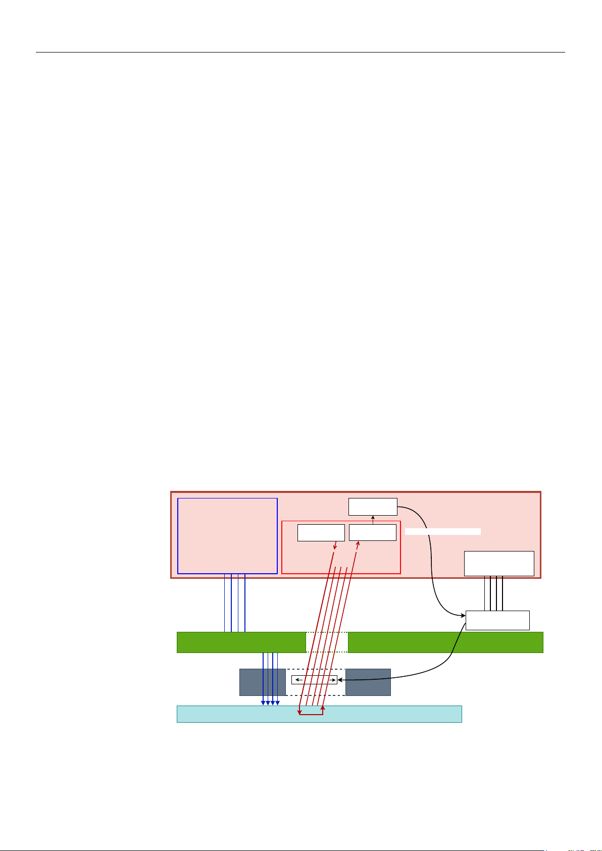
Figure 2 presents the system-level architecture of the Eclipse Dynamic probe card
during wafer-level testing. The tester provides both the electrical test program and the
optical test program. The optical path comprises a source/modulation stage and a detection
stage connected to the integrated FAU in the probe head, while the mechanical alignment
loop is closed through the controller and the piezoelectric drive electronics. The FAU
is integrated into the probe head together with the electrical probes, such that optical
and electrical contact are established on the same wafer site during probing. Rather than
actuating individual fibers independently, the system displaces the entire FAU as a single
rigid body in the X–Y plane, with differential actuation used for tilt compensation. This
architecture eliminates the need for external optical positioning stages and enables compact,
high-throughput wafer-level electro-optical testing.
Electrical Test
Testing program
Optical Test
Testing program
Optical
Modulator
Photoelectric
Converter
Optical Alignment Algorithm
Controller
Piezo Power Supplier
Piezo Voltage Boost
Probe Head
Align loop
Fiber Array Unit
PCB
Tester
Piezo
Wafer
Probes
Figure 2. System-level block diagram of the automated wafer-level photonic testing platform, show-
ing the tester, controller, optical source/detection chain, piezoelectric drive electronics, integrated
probe head, and wafer under test.
https://doi.org/10.3390/mi17050592
Micromachines 2026, 17, 592
10 of 34
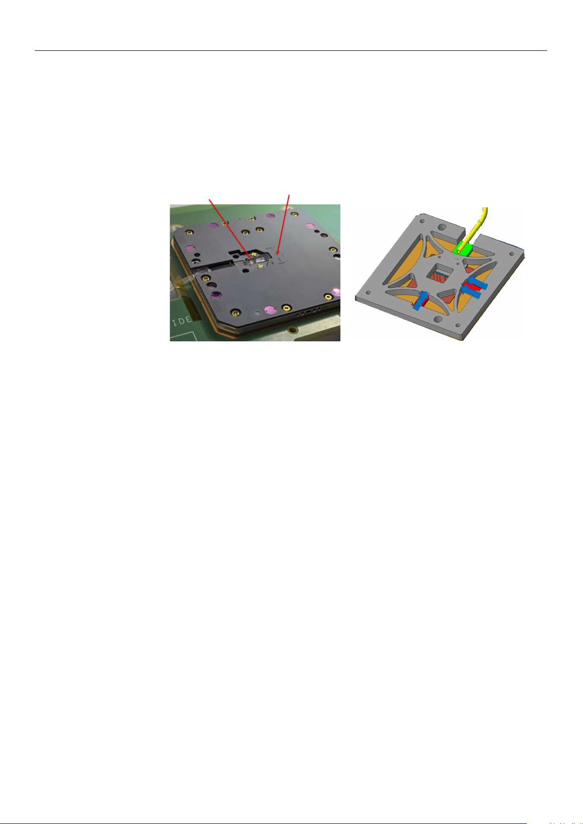
Structurally, the probe head consists of two ceramic layers with guiding holes for
the electrical probes, separated by a metallic flexure structure, as illustrated in Figure 3.
Based on the patented mechanical architecture [
41
], this flexure supports the integrated
FAU and is actuated by three piezoelectric elements: one actuator controls the X-axis, while
two parallel actuators (Y1 and Y2) control the Y-axis. Differential driving of Y1 and Y2
provides the rotational tilt compensation required for precise optical alignment, whereas
the vertical Z-axis approach is handled by the prober chuck rather than by the integrated
piezoelectric stage.
Probes
FAU
(a) (b)
Figure 3. Eclipse Dynamic Probe Head architecture. (a) Complete probe head assembly showing
electrical probes and FAU integration. (b) Internal flexure mechanism showing the piezoelectric
actuators (X, Y1, Y2) used for nanometric alignment, with their respective positions marked in
blue [8].
The embedded FAU is a configurable interface rather than a fixed-format optical array.
In particular, the number of fibers and the fiber pitch are selected according to the PIC
under test, including the number of optical channels, the spacing between input/output
ports, and the pitch of the access couplers or waveguides on the chip. Accordingly, the
FAU geometry is customized to match the DUT layout while remaining compatible with
the mechanical and electrical constraints of the integrated probe head. More generally,
the underlying probe-head concept supports multi-channel optical interfacing through an
optical distribution element comprising a plurality of waveguides aligned to the probe-
head structure by dedicated alignment features [
41
]. Because the input and output fibers
are fixed within one rigid FAU block, they are aligned simultaneously as a unified assembly
rather than sequentially.
The actuators are controlled through the probe card PCB, driven by the tester system.
The operating voltage range is 0–120 V, corresponding to a total displacement range of
15
µ
m
×
15
µ
m in the X–Y plane. Under typical operating conditions, the system achieves
positioning resolution better than 1 nm, enabling precise alignment to grating couplers
with typical mode-field diameters of 10–15 µm.
Because the probe head is a highly compact integrated electro-optical environment,
embedding physical displacement sensors for closed-loop optical alignment would in-
troduce undesirable spatial and packaging complexity. Therefore, the system relies on
open-loop control. Although the complete hardware architecture and containment-element
kinematics have been defined in foundational patents and prior literature [
7
,
8
,
41
], the
remainder of this study focuses specifically on the computational efficiency, reliability, and
optimization of the automated optical alignment algorithms.
https://doi.org/10.3390/mi17050592