mi17050592.pdf - 第21页
Micromachines 2026 , 17 , 592 21 of 34 ( c ) Cross ( d ) Local BO ( e ) Global BO ( f ) V ar-Grad ( g ) Fix-Grad Figure 8. Comparison of all seven alignment algorithms on the same mock scan scenario. Each panel shows the…
Micromachines 2026, 17, 592
20 of 34
• Fixed Gradient Ascent (Fix-Grad):
The Fix-Grad method is a traditional gradient search technique with fixed step sizes
that halve upon observing no improvement. The procedure begins with a cross-scan
(7 points per axis), and then iteratively explores neighbors in the cardinal directions
(initial step 4 V or
∼
0.5
µ
m, minimum 1 V or
∼
0.125
µ
m) to identify the optimal ascent
direction, as shown in Algorithm 7:
Algorithm 7 Fix-Grad
1: // Initial cross-scan (7 points per axis)
2: for V
x
∈ {0, 20, 40, 60, 80, 100, 120} do
3: Sample power at (V
x
, 60)
4: end for
5: Find x
max
with highest power
6: for V
y
∈ {0, 20, 40, 60, 80, 100, 120}\ {60} do
7: Sample power at (x
max
, V
y
)
8: end for
9: (x
0
, y
0
) ← best point from cross-scan
10: Measure P
current
at (x
0
, y
0
)
11: δ ← 4 (initial step size)
12: while δ ≥ 1 do
13: Measure power at (x + δ, y), (x −δ, y), (x, y + δ), (x, y −δ)
14: (x
′
, y
′
, P
′
) ← best neighbor
15: if P
′
> P
current
then
16: (x, y, P
current
) ← (x
′
, y
′
, P
′
)
17: else
18: δ ← δ/2 (reduce step size)
19: end if
20: end while
21: Move to (x, y)
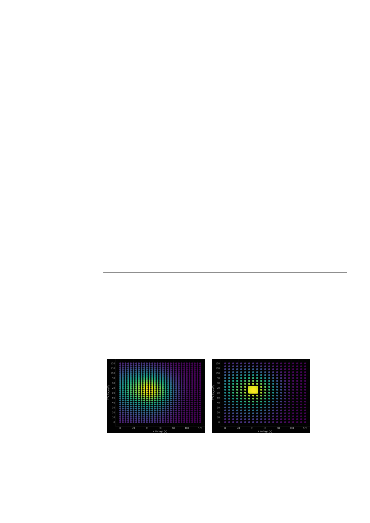
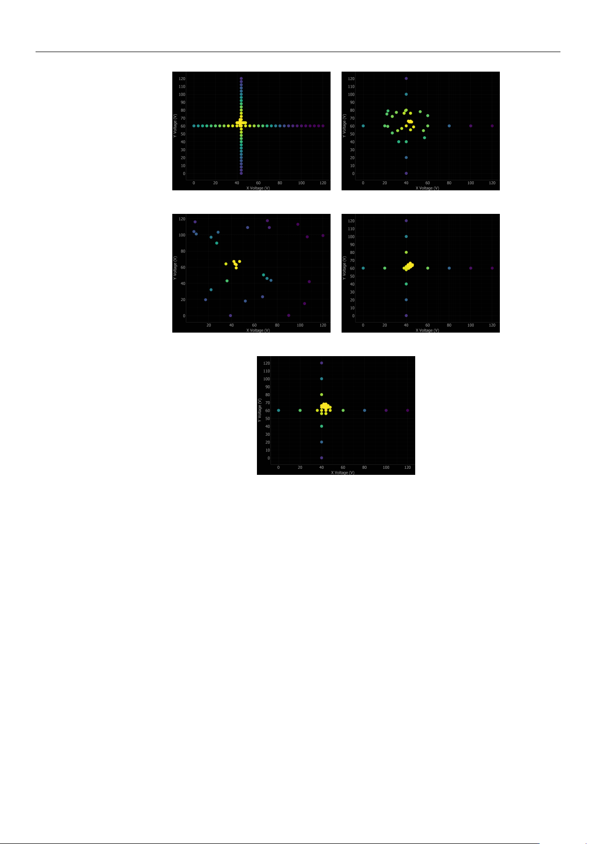
Figure 8 illustrates the application of all seven alignment algorithms to a representative
mock scan scenario centered at (60 V, 60 V), providing a direct visual comparison of
their respective search strategies. Each algorithm navigates the 120 V
×
120 V operating
range using a distinct optimization philosophy: Ref-Coarse and Ref-Coarse+Fine employ
systematic raster scans; Cross scan utilizes dimensional reduction via orthogonal axis
scanning; Local and Global BO implement intelligent sampling guided by Gaussian Process
uncertainty; and Variable and Fix-Grad utilize hill-climbing techniques to track the local
power gradient.
(a) Ref-Coarse (b) Ref-Coarse+Fine
Figure 8. Cont.
https://doi.org/10.3390/mi17050592
Micromachines 2026, 17, 592
21 of 34
(c) Cross (d) Local BO
(e) Global BO (f) Var-Grad
(g) Fix-Grad
Figure 8. Comparison of all seven alignment algorithms on the same mock scan scenario. Each
panel shows the search path of the algorithm overlaid as discrete colored measurement points,
where the color intensity represents the measured optical power (ranging from dark purple for low
power to bright yellow for the highest power). The figures demonstrate distinct search strategies:
(a,b) exhaustive raster scanning, (c) dimensional reduction, (d,e) BO with intelligent sampling,
(f,g) gradient-based hill climbing.
3.5. Performance Metrics and Statistical Analysis
Following best practices for algorithm comparison [
18
], we employ multiple evalua-
tion approaches to ensure a robust assessment. First, for each algorithm on each problem
instance, we record four individual metrics: a binary success indicator (defined as converg-
ing to
≥
95% of the global maximum), the total number of measurement steps required,
the total elapsed time including all movements and settling delays, and the final coupling
accuracy (the achieved power divided by the global maximum power).
For the initial performance assessment, we compute a core set of aggregate quantitative
indicators. The primary metric is the overall success rate, strictly defined as the percentage
of alignment problems that were resolved successfully. Furthermore, we calculate central
tendency metrics across all trials—specifically the mean number of alignment steps, total
execution time, and final coupling accuracy. It should be noted that when reporting these
average values, appropriate statistical caveats must be applied to account for the frequently
non-normal distributions inherent in optimization data.
https://doi.org/10.3390/mi17050592

Micromachines 2026, 17, 592
22 of 34
To rigorously account for this non-normal distribution of convergence steps, particu-
larly as the number of test scenarios increases, we employ data profiles [
40
]. A data profile
plots the fraction of problems solved as a function of the number of function evaluations
(measurement steps):
ρ
s
(k) =
1
|P|
|{p ∈ P : n
s,p
≤ k}| (6)
where
P
is the set of test problems,
s
is a solver (algorithm),
n
s,p
is the number of steps
required by solver
s
on problem
p
, and
k
is the step budget. Data profiles provide a
complete picture of algorithm performance by showing not just average behavior, but the
full distribution of convergence speeds. An algorithm with a steep data profile quickly
solves most problems, while a shallow profile indicates slower or less reliable convergence.
In this work, data profiles are generated for the experimental results and for each specific
simulation scenario (HS-H, HS-NH, LS-H, and LS-NH), enabling a comprehensive statistical
comparison of algorithm performance across all operating conditions.
4. Results
4.1. Experimental Results
The algorithms are ranked based on a composite evaluation considering four critical
metrics: (1) success rate, which is the primary criterion for production deployment; (2) av-
erage alignment time, reflecting throughput impact; (3) final accuracy, indicating optical
coupling quality; and (4) average number of steps, representing measurement efficiency.
Algorithms with 100% success rate are prioritized, then ranked by alignment time. Those
with lower success rates are ranked lower regardless of speed, as unreliable alignment
requires manual intervention and severely impacts production throughput.
Table 1 summarizes the performance of all seven algorithms across the eight experi-
mental coupling scenarios.
Table 1. Experimental alignment results across 8 coupling scenarios. Algorithms ranked by combined
performance considering success rate, time, accuracy, and measurement efficiency. Results obtained
with baseline algorithm parameters.
Rank Method Success Rate Avg Time (a.u.) Avg Accuracy (%) Avg Steps
1 Local BO 100% 99.87 98.24 26.5
2 Fix-Grad 100% 154.01 99.18 69.0
3 Global BO 87.5% 175.19 97.60 37.4
4 Ref-Coarse+Fine 87.5% 334.11 98.31 600.3
5 Cross 75.0% 36.63 96.84 80.0
6 Var-Grad 75.0% 59.28 95.99 22.5
7 Ref-Coarse 75.0% 410.90 96.81 961.0
Experimental results indicate that the Local BO method achieves superior overall
performance, delivering a 100% success rate, 98.24% accuracy, and rapid convergence
(26.5 steps, 99.87 a.u.). This hybrid approach successfully balances exploration and ex-
ploitation via cross-scan initialization followed by Bayesian refinement. The Fix-Grad
algorithm similarly achieves absolute reliability (100% success) alongside a marginally
higher accuracy of 99.18%, although its systematic neighborhood exploration demands
increased execution metrics (69.0 steps, 154.01 a.u.). In contrast, Global BO demonstrates
strong general performance (97.60% accuracy, 37.4 steps) but yields an 87.5% success rate,
indicating occasional difficulty navigating complex landscapes where optimal coupling re-
gions remain distant from initial random samples. Furthermore, while the Ref-Coarse+Fine
strategy provides adequate accuracy (98.31%), the exhaustive measurement requirement
https://doi.org/10.3390/mi17050592